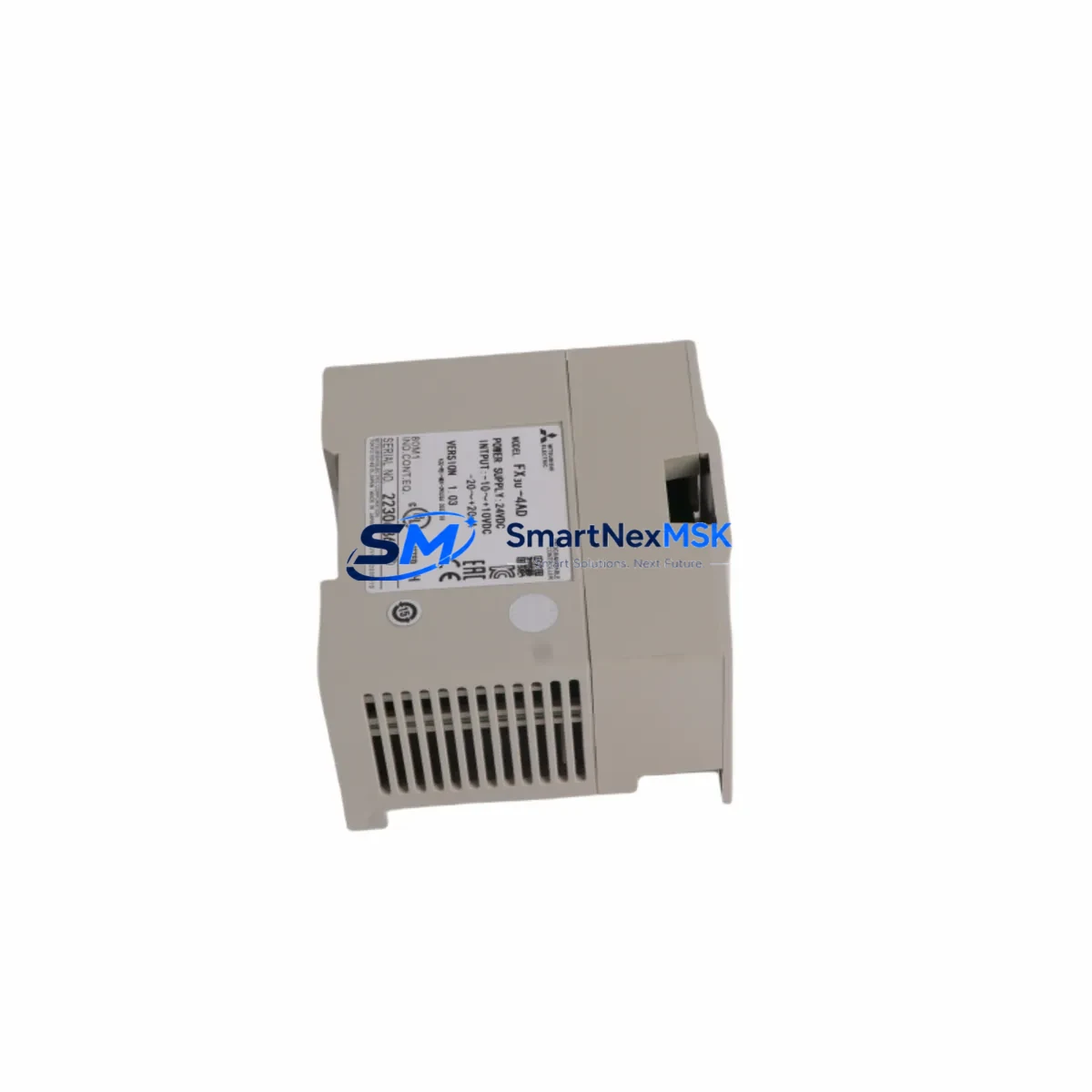
Mitsubishi FX3U-4AD Maintenance-Ready Spare for FX3U Automation
The Mitsubishi Electric FX3U-4AD is a 4-channel analog input expansion module designed for the MELSEC FX3U series programmable logic controller platform. In industrial maintenance environments — from automotive assembly lines to chemical process plants — the FX3U-4AD plays a critical role in acquiring real-time analog signals from field sensors, transmitters, and transducers. When this module fails or degrades, the entire analog acquisition loop is compromised, triggering unplanned downtime and production loss.
Stocking a verified replacement FX3U-4AD is a fundamental element of any proactive maintenance strategy. Whether you are executing a planned shutdown inspection, responding to a fault alarm, or managing a long-term spare parts inventory for aging MELSEC FX3U systems, having a tested, original-specification module on hand reduces mean time to repair (MTTR) and protects operational continuity.
Spare Maintenance Table
| Parameter | Specification |
|---|---|
| Model / SKU | FX3U-4AD |
| Brand | Mitsubishi Electric |
| Series | MELSEC FX3U |
| Module Type | 4-Channel Analog Input Expansion Module |
| Input Channels | 4 (voltage / current selectable per channel) |
| Voltage Input Range | -10 V to +10 V DC |
| Current Input Range | 4–20 mA DC |
| Resolution | 12-bit (1/4000) |
| Conversion Speed | Approx. 6 ms / 4 channels |
| Power Supply | Supplied via FX3U main unit bus (5 VDC internal) |
| Isolation | Photocoupler isolation between analog and digital circuits |
| Compatible PLCs | FX3U, FX3UC (with adapter), FX3G (with adapter) |
| Installation | Direct left-side expansion on FX3U main unit |
| Operating Temperature | 0°C to 55°C |
| Storage Temperature | -25°C to 75°C |
| Humidity | 5% to 95% RH (non-condensing) |
| Weight | Approx. 180 g |
| Origin | Japan |
| Warranty | 12 Months — Tested & Verified Before Shipment |
| Maintenance Recommendation | Inspect terminal connections, verify channel calibration, check for drift on active channels during planned shutdown |
Maintenance Planning for Continuous Operation
When a maintenance or procurement engineer identifies the FX3U-4AD as a replacement requirement, the scope of inspection should extend beyond the module itself. A thorough control cabinet audit during the same maintenance window significantly reduces the risk of repeat failures and secondary faults.
Begin by verifying the FX3U-PSU-A or equivalent 24 VDC power supply module — analog input modules are sensitive to power rail noise and voltage sag, which can cause erratic readings or module lockup before visible hardware failure. Inspect the FX3U main CPU unit (such as the FX3U-32MR/ES or FX3U-64MT/ES) for firmware version compatibility with the replacement module, as older CPU firmware may not correctly initialize a new FX3U-4AD.
Check the FX3U-4DA analog output module if it is installed in the same expansion chain — a shared bus fault can affect both input and output modules simultaneously. Review the FX3U-232ADP-MB or FX3U-485ADP-MB communication adapters for any communication timeout errors that may have been masked by the analog fault alarm.
At the field wiring level, inspect all terminal blocks connected to the FX3U-4AD’s analog input terminals. Loose or corroded terminals on the FX3U-CNV-BD or direct screw terminals are a common root cause of signal drift and intermittent channel faults. If the system uses signal isolators or loop-powered transmitters, verify that the isolator output is within the module’s rated input range before reconnecting.
For systems using the FX3U-ENET Ethernet module or FX3U-USB-BD for remote monitoring, confirm that the network connection is restored and that the SCADA or HMI — such as a GOT2000 series GT2107 or GT2310 — is correctly reading the analog channel data after module replacement. A mismatch in buffer memory addresses between the old and new module can cause the HMI to display incorrect process values even after a successful hardware swap.
Finally, review the fuse and circuit protection for each analog input channel. If the previous module failed due to an overvoltage event, the field wiring may still carry the fault condition. Installing a replacement FX3U-4AD without clearing the root cause will result in immediate re-failure.
Site Replacement Workflow
Step 1 — Power Down & Isolate: De-energize the FX3U main unit and all expansion modules. Lock out the control cabinet per site LOTO procedures. Disconnect all analog field wiring from the FX3U-4AD terminal block and label each wire for accurate reconnection.
Step 2 — Module Removal: Release the DIN rail mounting clip and slide the FX3U-4AD away from the expansion bus connector. Inspect the bus connector pins on both the removed module and the adjacent unit for damage or contamination.
Step 3 — Replacement Installation: Align the new FX3U-4AD with the expansion bus connector on the FX3U main unit. Press firmly until the connector seats fully and the DIN rail clip engages. Reconnect all analog field wiring per the original terminal labeling, verifying polarity for current-input channels.
Step 4 — Power-Up & Verification: Restore power to the FX3U system. Use GX Works2 or GX Works3 to read the buffer memory (BFM) of the new FX3U-4AD and confirm that all four channels are returning valid analog values. Compare readings against known process values or a calibrated signal source.
Step 5 — System Handover: Document the replacement in the maintenance log, including the date, replaced module serial number, and post-replacement channel readings. Update the spare parts inventory to trigger reorder of a standby FX3U-4AD unit.
This workflow is compatible with direct replacement of legacy FX2N-4AD installations in systems that have been upgraded to the FX3U platform, provided that the PLC program buffer memory addresses have been updated accordingly.
Spare Parts Support FAQ
Q1: Is this FX3U-4AD an original Mitsubishi Electric component?
Yes. All FX3U-4AD units supplied by SMARTNEXMSK are sourced as original Mitsubishi Electric components. Each unit undergoes functional testing — including analog channel verification across voltage and current input ranges — prior to shipment. A 12-month warranty is provided from the date of delivery.
Q2: Can the FX3U-4AD replace an FX2N-4AD in an upgraded system?
The FX3U-4AD is not a direct drop-in replacement for the FX2N-4AD due to differences in buffer memory (BFM) mapping and module addressing. A program modification in GX Works2 is required to remap the analog channel data. SMARTNEXMSK recommends consulting the FX3U-4AD User’s Manual (JY997D16601) before proceeding with cross-series substitution.
Q3: What is the recommended spare parts stocking strategy for FX3U analog modules?
For facilities operating more than three FX3U systems, maintaining a minimum of one FX3U-4AD and one FX3U-4DA in the on-site spare parts cabinet is recommended. For critical processes with no redundancy, a 1:1 hot-spare ratio is advisable. SMARTNEXMSK supports long-term supply agreements to ensure consistent availability as the FX3U platform ages.
Q4: How is the FX3U-4AD tested before shipment?
Each unit is powered up and connected to a test FX3U main unit. All four analog input channels are verified using calibrated voltage and current sources. Buffer memory read/write operations are confirmed via GX Works2. Units that do not meet original Mitsubishi Electric performance specifications are rejected. A test report is available upon request.
© 2026 SMARTNEXMSK. All rights reserved.
Original Source: https://smartnexmsk.com
Contact: [email protected] | +86 18259474341