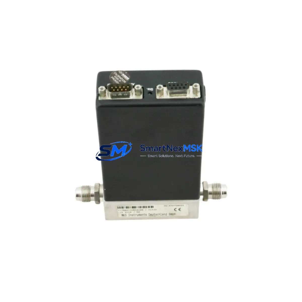
MKS 1179AX11CR14V26 Maintenance-Ready Spare for 1179 Automation: Spare Replacement & Industrial Downtime Risk Control
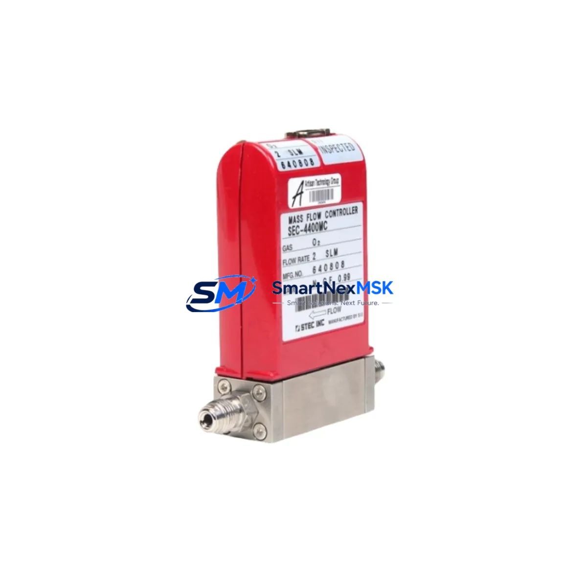
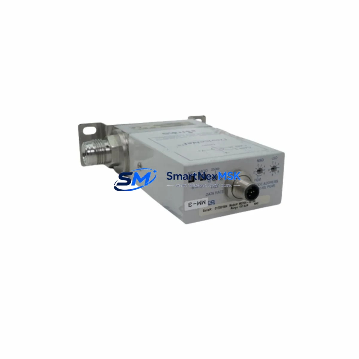
The MKS Instruments 1179AX11CR14V26 is a thermal mass flow controller (MFC) from the Mass-Flo® 1179 Series, widely deployed in semiconductor fabrication, chemical vapor deposition (CVD), etching, and precision process gas delivery systems. Carrying reference part numbers PF802-ADS, E17601520, and E19299450, this unit is engineered for accurate, repeatable gas flow measurement and control in demanding industrial environments. Maintaining a verified spare of the 1179AX11CR14V26 in your parts inventory is a proven strategy for minimizing unplanned downtime and protecting process continuity in critical automation lines.
Spare Maintenance Table
| Parameter | Specification / Detail |
|---|---|
| Part Number | 1179AX11CR14V26 |
| Reference Numbers | PF802-ADS / E17601520 / E19299450 |
| Brand | MKS Instruments |
| Series | Mass-Flo® 1179 Series |
| Product Type | Thermal Mass Flow Controller (MFC) |
| Typical Application | Semiconductor process gas control, CVD, ALD, etch, and precision gas delivery |
| Control Signal | Analog (0–5 VDC / 4–20 mA, configuration-dependent) |
| Communication | RS-232 / DeviceNet (model-dependent); compatible with MKS Type 247, PR4000B, and MultiGas controllers |
| Valve Type | Normally closed proportional solenoid valve |
| Wetted Materials | 316L SS body, Viton or Kalrez seals (process-dependent) |
| Operating Temperature | 0–50 °C ambient; process gas temperature per application spec |
| Mounting / Interface | Surface-mount (D-sub connector); compatible with standard MKS manifold and stick configurations |
| Origin | CN (manufactured / sourced) |
| Weight | 2,600 g |
| Warranty | 12 Months — tested before shipment |
| Compatibility | Direct replacement for legacy 1179A-series MFCs in MKS-based gas panels and process tool gas boxes |
| Maintenance Recommendation | Replace at first sign of flow drift, valve stiction, or zero-offset instability; recalibrate after installation |
Maintenance Planning for Continuous Operation
When a 1179AX11CR14V26 mass flow controller is flagged for replacement during a scheduled or emergency maintenance event, experienced process engineers know that the MFC itself is rarely the only component that warrants attention. A thorough inspection of the surrounding gas delivery and control infrastructure is essential to prevent repeat failures and ensure the system returns to full specification.
Begin with the upstream gas supply circuit: verify the inlet pressure regulator and check valve are within spec, as pressure excursions are a leading cause of MFC sensor drift and valve wear. Inspect the process gas line filter or purifier immediately upstream of the MFC — particulate contamination is a common root cause of valve seat damage in 1179-series units. If the tool uses a MKS Type 247 or PR4000B multi-channel readout and control unit, confirm that the setpoint signal and power supply rails are stable; a degraded power supply card can cause erratic flow control across all channels simultaneously.
Check the D-sub signal cable and connector between the MFC and the controller — pin corrosion or intermittent contact is frequently misdiagnosed as MFC failure. For systems using DeviceNet or RS-232 communication, verify the network termination resistors and cable shielding integrity. In multi-zone gas panels, inspect the pneumatic or solenoid isolation valves (such as MKS 99 Series or equivalent) that bracket the MFC; a leaking isolation valve will corrupt flow readings and accelerate MFC wear.
On the electrical side, test the 24 VDC instrument power supply feeding the MFC and associated instrumentation — voltage sag under load is a subtle but destructive condition. Review the terminal block wiring and grounding in the gas panel enclosure; poor grounding introduces noise on the analog setpoint and feedback signals, causing hunting and instability. If the system includes a signal isolator or analog I/O barrier between the PLC and the MFC controller, verify isolation resistance and signal fidelity.
For tools with integrated HMI or SCADA displays showing flow trends, use historical data to identify gradual drift before the next planned shutdown — this is the most cost-effective way to schedule 1179AX11CR14V26 replacements proactively rather than reactively. Finally, if the gas panel includes a pressure transducer or capacitance manometer (such as an MKS Baratron® 627 or 722 Series) on the downstream side of the MFC, cross-check its readings against the MFC output to confirm the replacement unit is performing within calibration tolerance after installation.
Site Replacement Workflow
Step 1 — Isolation & Lockout: Close upstream and downstream isolation valves. Purge the gas line with dry nitrogen per site safety procedures. De-energize the MFC signal cable and confirm zero flow on the controller display.
Step 2 — Documentation: Record the existing MFC serial number, calibration gas, full-scale range, and setpoint before removal. Photograph the wiring and connector orientation. This data is critical for configuring the replacement unit correctly.
Step 3 — Removal: Disconnect the D-sub signal connector. Remove the MFC from the manifold or stick mount, taking care not to contaminate the inlet/outlet ports. Cap all open ports immediately.
Step 4 — Replacement Unit Verification: Confirm the 1179AX11CR14V26 replacement unit matches the original calibration gas, full-scale range, and valve configuration. Our units are tested and verified before shipment; retain the test certificate for your maintenance records.
Step 5 — Installation & Leak Check: Mount the replacement MFC, reconnect the signal cable, and perform a helium or nitrogen leak check on all fittings. Restore gas supply pressure gradually.
Step 6 — Functional Verification: Apply a known setpoint via the MKS Type 247 or PR4000B controller and verify the actual flow reading matches within the specified accuracy band. Log the zero and span readings in your CMMS. Resume normal process operation.
This workflow is compatible with legacy 1179A-series installations and does not require tool downtime beyond the physical swap and leak check — typically 1–3 hours for a prepared maintenance team with a verified spare on hand.
Spare Parts Support FAQ
Q1: What is the shelf life and storage requirement for a 1179AX11CR14V26 spare unit?
When stored in the original packaging in a clean, dry environment at 15–30 °C with relative humidity below 60%, the 1179AX11CR14V26 maintains full functional integrity for up to 24 months. We recommend annual inspection of stored spares and re-verification of zero and span before installation if the unit has been in storage for more than 12 months.
Q2: How is compatibility with my existing gas panel confirmed before shipment?
Compatibility is verified against the original MKS 1179A-series specification using the full SKU (1179AX11CR14V26) and reference numbers (PF802-ADS, E17601520, E19299450). Each unit undergoes functional testing — including valve actuation, flow sensor response, and signal output verification — prior to shipment. A test report is included with every order.
Q3: Does the 12-month warranty cover field failures caused by process gas contamination?
The 12-month warranty covers manufacturing defects and functional failures under normal operating conditions. Failures attributable to process gas contamination, overpressure events, or installation errors are assessed case by case. We recommend providing the maintenance log and failure description when submitting a warranty claim — our technical team will advise on root cause and resolution.
Q4: Can this unit replace older 1179A-series MFCs with different connector pinouts or communication protocols?
The 1179AX11CR14V26 is designed as a direct mechanical and electrical replacement for standard 1179A-series configurations. If your existing installation uses a non-standard pinout, custom calibration gas, or a legacy communication protocol variant, please contact our sales team with your original part number and system details before ordering. We can confirm compatibility or identify the correct variant to ensure a drop-in replacement.
© 2026 SMARTNEXMSK. All rights reserved.
Original Source: https://smartnexmsk.com
Contact: [email protected] | +86 18259474341