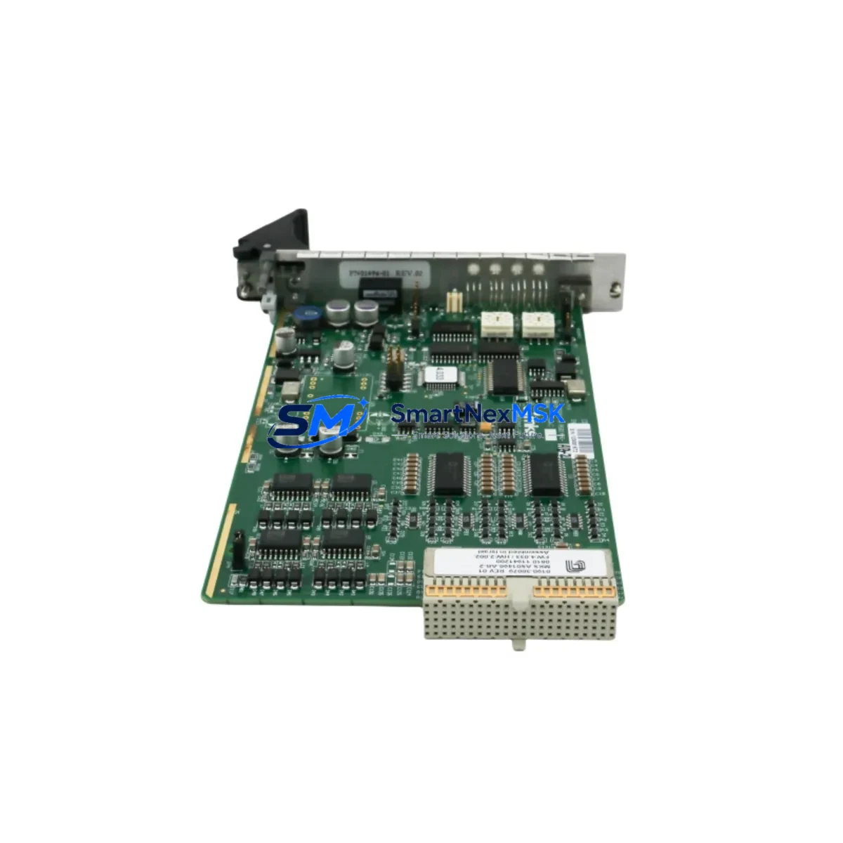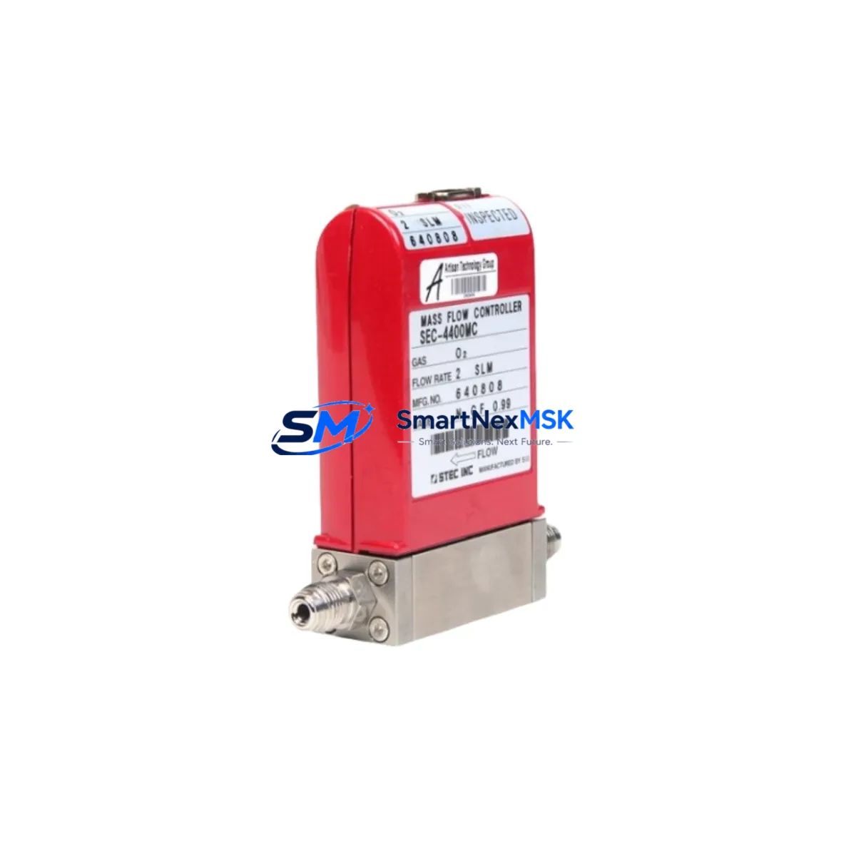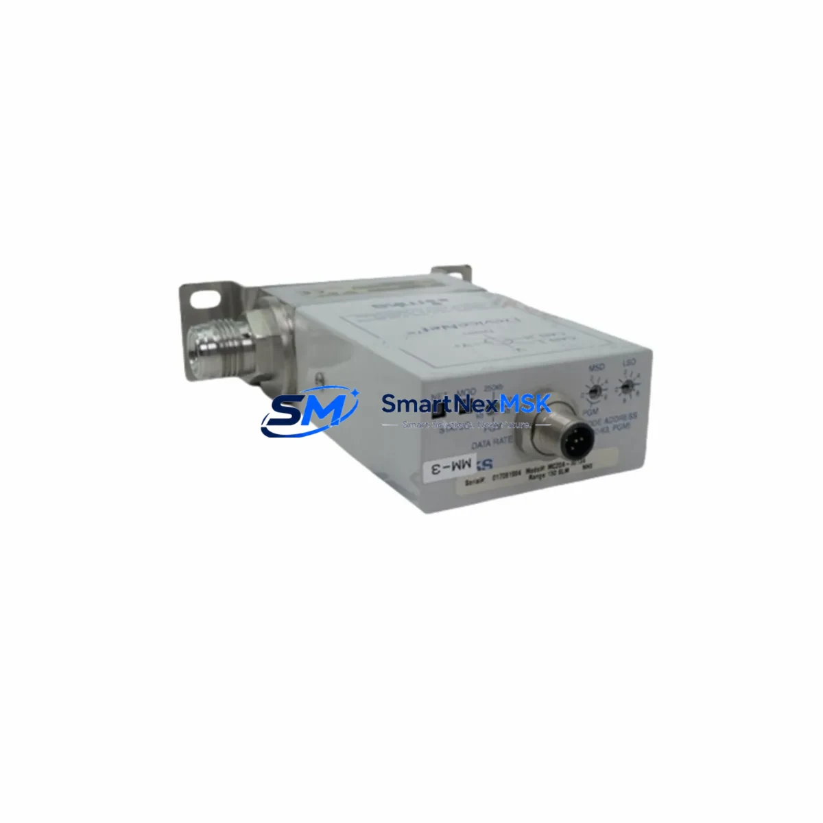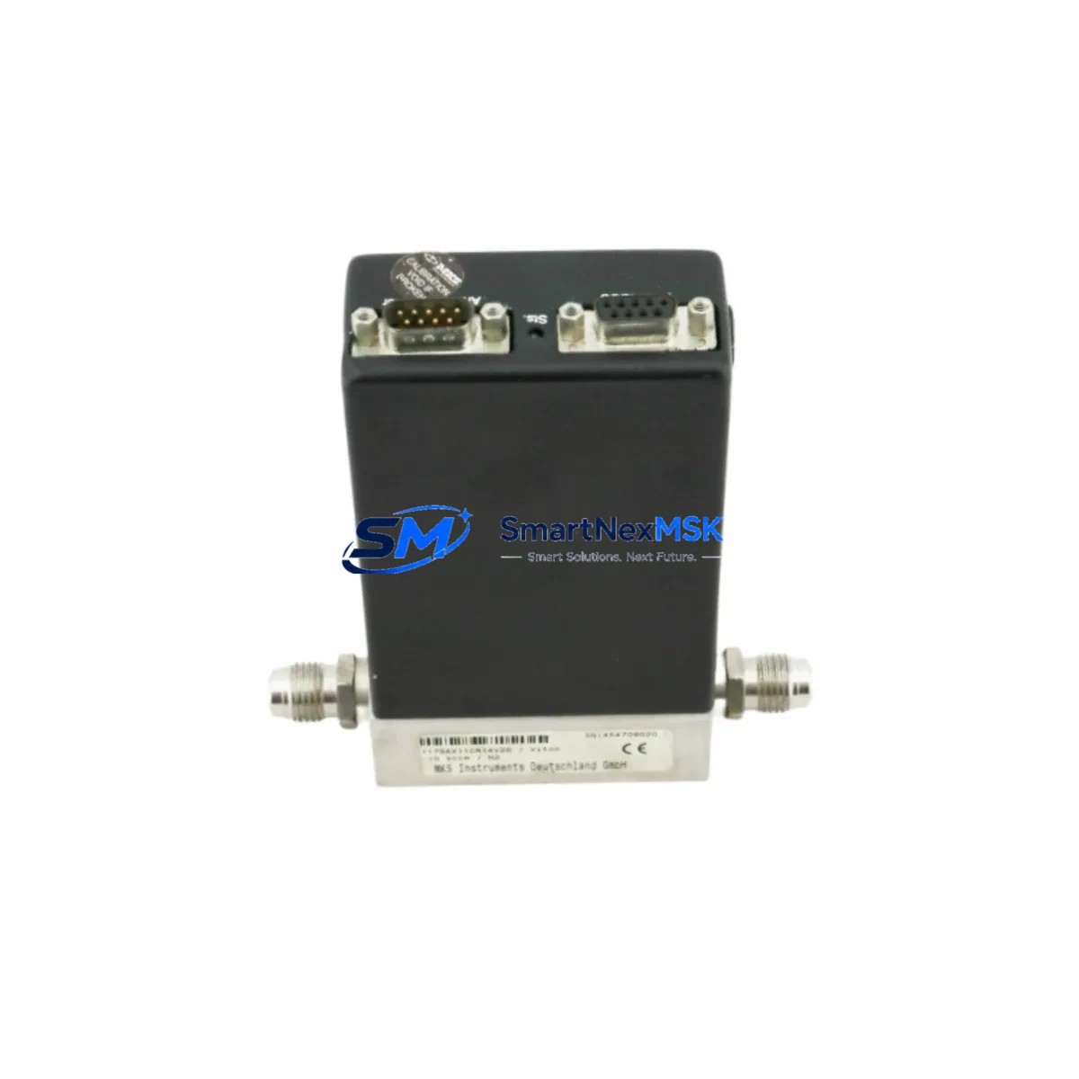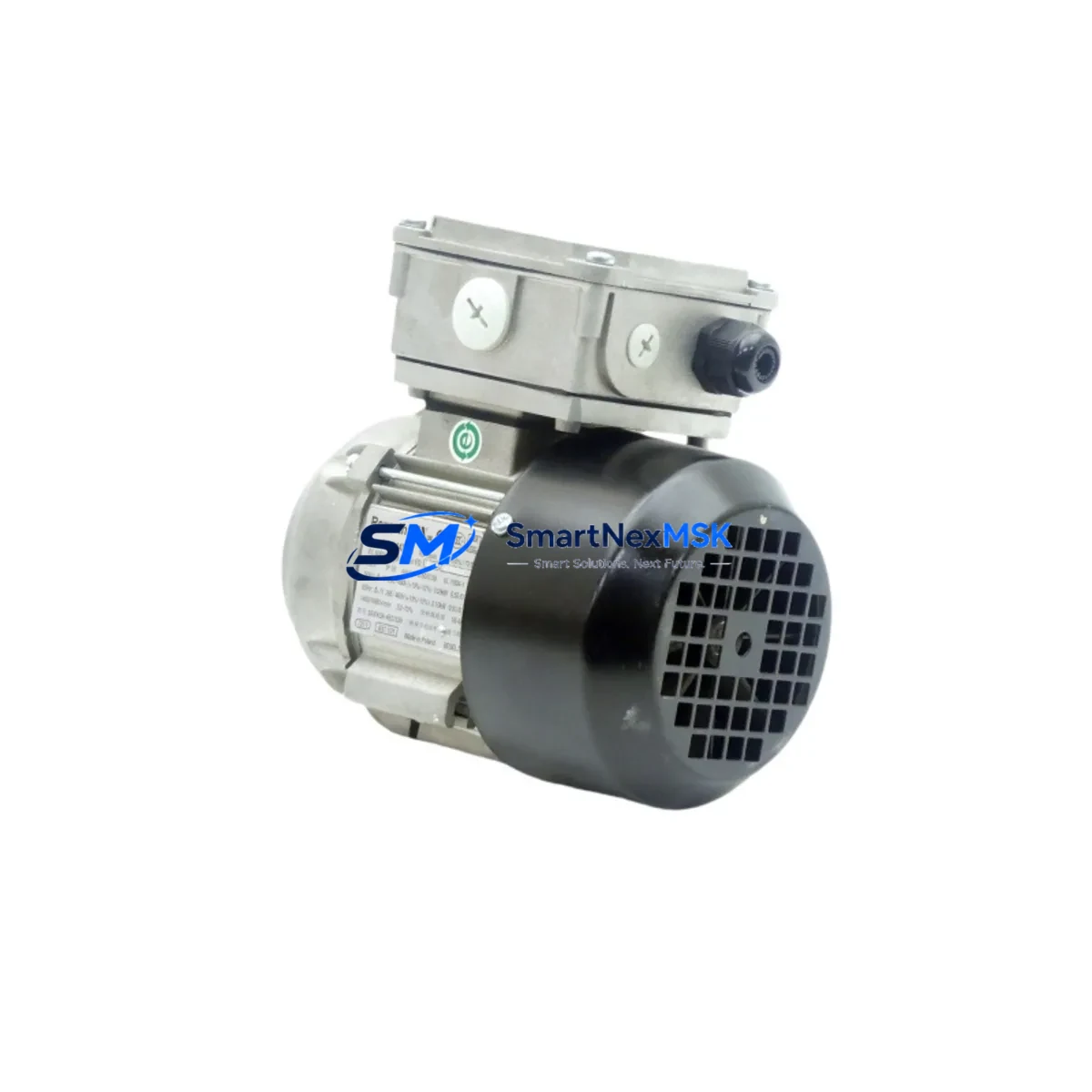
MKS 253B-15488 Retrofit-Ready Throttle Control Valve for 253B Series Control Systems
The MKS 253B-15488 is a precision throttle control valve engineered for seamless integration into legacy 253B Series vacuum process control systems. Whether you are managing a scheduled upgrade, responding to an end-of-life notification on your existing valve assembly, or sourcing a verified replacement for a discontinued component, the 253B-15488 delivers the dimensional accuracy, pressure range compatibility, and communication interface alignment required for a smooth, low-risk retrofit. This unit is stocked and available for immediate dispatch, backed by a 12-month warranty covering manufacturing defects and functional performance.
Industrial facilities running MKS-based vacuum process lines — including CVD, PVD, etch, and diffusion furnace applications — frequently encounter the challenge of replacing aging throttle valves without disrupting upstream pressure control loops or downstream mass flow controller (MFC) calibration. The 253B-15488 addresses this directly: its form factor matches the original 253B Series mounting envelope, its analog and digital I/O pinout is compatible with standard MKS Type 252 and Type 651 pressure controller interfaces, and its actuator response curve has been validated against the original OEM specification.
Upgrade Compatibility Table
| Parameter | 253B-15488 Specification | Retrofit Notes |
|---|---|---|
| Valve Type | Pendulum Throttle Control Valve | Direct replacement for 253B Series pendulum valves |
| Flange Interface | ISO-K / CF-compatible (per OEM spec) | Verify flange size (63, 100, 160 mm) before ordering |
| Control Interface | Analog 0–10 VDC / RS-232 optional | Compatible with MKS Type 651 and Type 252 controllers |
| Pressure Range | 1 × 10⁻⁴ to 1000 Torr (process dependent) | Confirm process setpoint range with existing controller |
| Power Supply | 24 VDC (±10%) | Check cabinet power rail capacity before installation |
| Communication Protocol | Analog + optional RS-232 | No protocol migration required for standard 253B installations |
| Mounting Orientation | Vertical or horizontal (per OEM) | Match existing installation orientation |
| Warranty | 12 Months | Covers manufacturing defects and functional performance |
Retrofit Planning for Existing Automation Systems
A successful 253B-15488 retrofit begins well before the valve arrives on-site. Engineers should pull the existing wiring diagram for the control cabinet and cross-reference the terminal block assignments against the 253B-15488 I/O connector pinout. In most 253B Series installations, the valve interfaces with a MKS Type 651C pressure controller or a Type 252A flow ratio controller via a 15-pin D-sub connector. Confirm that the cable harness — typically a shielded, twisted-pair assembly — is in serviceable condition and that the connector shell is not corroded or mechanically damaged.
On the power side, the 253B-15488 draws 24 VDC from the control cabinet power supply. Before installation, verify that the existing DIN-rail power supply (commonly a 24 VDC / 5 A or 10 A unit) has sufficient headroom to support the valve actuator’s inrush current during open/close cycles. If the cabinet also powers a MKS Type 1179A mass flow controller, a Type 670 signal conditioner, or a Baratron capacitance manometer (such as the Type 627D or Type 722A), calculate the total load and confirm the power budget before proceeding.
For systems that include a programmable logic controller (PLC) — such as a Siemens S7-300 series CPU or an Allen-Bradley ControlLogix rack — the valve position feedback signal (0–10 VDC analog output) must be mapped to the correct analog input module. If the original program uses a scaled engineering unit block for pressure setpoint ramping, verify that the scaling parameters remain valid after the valve swap. No firmware changes are required on the 253B-15488 for standard analog control loops, but if the system uses RS-232 serial communication for remote valve positioning, confirm the baud rate and handshake settings match the host controller configuration.
Backplane and rack considerations are minimal for this valve, as the 253B-15488 is a standalone field device rather than a rack-mounted I/O module. However, if the valve is installed in a cluster tool or multi-chamber system sharing a common vacuum manifold, coordinate the replacement schedule with the chamber isolation valve sequence to avoid cross-contamination or unintended pressure excursions in adjacent process chambers. A MKS Type 153 or Type 155 isolation valve on the foreline is typically used for this purpose and should remain closed during the swap.
Downtime Control During System Migration
Minimizing unplanned downtime during a throttle valve replacement requires a structured pre-shutdown checklist. Before venting the process chamber, save the current recipe parameters from the process controller — including pressure setpoints, ramp rates, and valve position limits — to a backup file or a printed record. If the system uses a SCADA or DCS platform (such as a Wonderware InTouch HMI or a Yokogawa CENTUM VP station), capture a screenshot of the current valve trend display and note the steady-state valve position percentage at the nominal process pressure.
During the physical swap, tag and photograph each terminal connection before disconnecting. The 253B-15488 uses the same connector footprint as the outgoing valve, so reconnection is straightforward, but photographic documentation eliminates ambiguity if the wiring labels have faded. After mechanical installation and leak check (helium leak test or nitrogen pressure hold, per site procedure), perform a slow pump-down to base pressure while monitoring the valve position feedback on the controller display. Compare the feedback signal to the pre-swap baseline to confirm the actuator is responding correctly before resuming process recipes.
For facilities with strict OEE targets, consider staging the replacement during a scheduled preventive maintenance window rather than waiting for a failure event. The 253B-15488 is available from stock, and pre-positioning a spare unit in the site stores — alongside compatible consumables such as O-ring kits and foreline trap elements — reduces mean time to repair (MTTR) significantly. All units shipped by SMARTNEXMSK are function-tested prior to dispatch and include a test report confirming valve travel, leak rate, and control interface continuity.
Retrofit Support FAQ
Q: Is the MKS 253B-15488 a direct drop-in replacement for all 253B Series throttle valves?
A: The 253B-15488 (cross-referenced as 0050-61196 / 0050-61197) is compatible with the standard 253B Series mounting envelope and control interface. However, flange size variants exist within the 253B family. Confirm your existing valve’s flange diameter (63 mm, 100 mm, or 160 mm ISO-K) and connector type before ordering. Our technical team can verify compatibility using your existing valve’s serial number or part marking.
Q: Do I need to modify my PLC program or HMI screens after installing the 253B-15488?
A: In the vast majority of 253B Series installations using standard analog control (0–10 VDC), no PLC program changes are required. The valve position feedback signal and control input are electrically identical to the original unit. If your system uses RS-232 serial communication, verify that the baud rate and protocol settings in your host controller match the 253B-15488 default configuration (9600 baud, 8N1 is typical). HMI faceplate graphics do not require modification for analog-controlled installations.
Q: What commissioning steps are required after installation?
A: After mechanical installation and leak verification, perform a full-travel calibration cycle: command the valve to 0% (fully closed) and 100% (fully open) via the controller and confirm the feedback signal reaches the expected endpoints (0 VDC and 10 VDC respectively). Then run a slow pump-down to process base pressure and verify that the pressure controller achieves setpoint within the expected time. Document the as-found and as-left valve position at nominal process pressure for your maintenance records.
Q: What does the 12-month warranty cover, and what is the return process?
A: The 12-month warranty covers manufacturing defects, actuator mechanism failures, and control interface faults under normal operating conditions. It does not cover damage resulting from incorrect installation, over-pressure events, or chemical contamination. To initiate a warranty claim, contact [email protected] with your order number, installation date, and a description of the fault. All units are function-tested and include a test report at time of shipment, providing a baseline for warranty evaluation.
© 2026 SMARTNEXMSK. All rights reserved.
Original Source: https://smartnexmsk.com
Contact: [email protected] | +86 18259474341