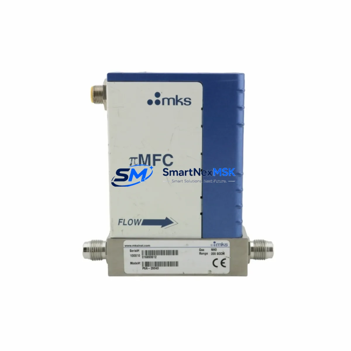
MKS P8A-29343 Maintenance-Ready Spare P-Series MFC: Spare Replacement & Industrial Downtime Risk Control
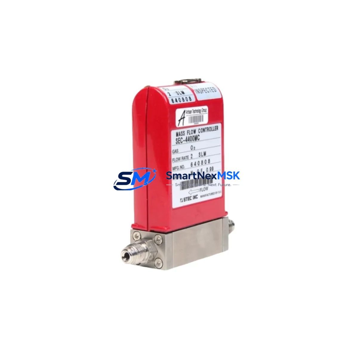
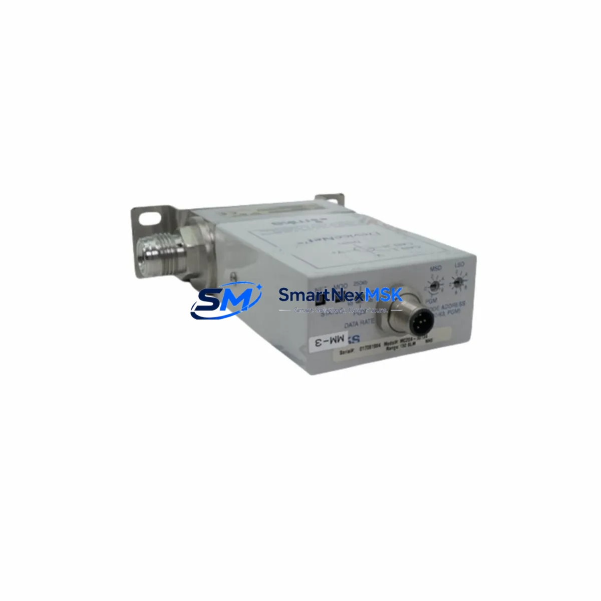
The MKS P8A-29343 (also cross-referenced as P5A-28219 and P8A-29344) is an original MKS Instruments P-Series pressure-insensitive mass flow controller engineered for precision gas flow management in semiconductor fabrication, CVD, ALD, etch, and related high-purity process environments. As a maintenance-ready spare, this unit is sourced, inspected, and dispatched to support rapid field replacement, minimizing unplanned downtime and protecting process continuity in critical automation systems.
For maintenance engineers and procurement teams managing aging semiconductor tool fleets or multi-tool fabs, holding a verified spare of the MKS P8A-29343 in your on-site buffer stock is a proven strategy to eliminate lead-time risk. MKS P-Series MFCs are widely deployed across OEM platforms including Applied Materials, Lam Research, Tokyo Electron, and Novellus systems, making this part a high-priority line item in any preventive maintenance BOM.
Spare Maintenance Table
| Parameter | Specification / Detail |
|---|---|
| Part Number (Primary) | P8A-29343 |
| Cross-Reference SKUs | P5A-28219 / P8A-29344 |
| Brand | MKS Instruments |
| Series | P-Series (Pressure-Insensitive MFC) |
| Product Type | Mass Flow Controller (MFC) |
| Operating Principle | Pressure-insensitive thermal mass flow measurement |
| Typical Gas Compatibility | N₂, Ar, O₂, H₂, NF₃, SiH₄, and process-specific gases (confirm with datasheet) |
| Communication Interface | Analog (0–5 VDC / 4–20 mA) or DeviceNet / RS-485 (model-dependent) |
| Inlet/Outlet Connection | VCR face-seal fittings (standard); confirm port size per installation drawing |
| Power Supply | ±15 VDC or +24 VDC (model-dependent; verify against tool wiring diagram) |
| Operating Environment | Cleanroom-compatible; semiconductor fab, CVD, ALD, etch process tools |
| Origin | USA (MKS Instruments) |
| Compatibility | Direct replacement for P8A-29343, P5A-28219, P8A-29344 in P-Series installations |
| Installation | Drop-in replacement; verify gas line purge and zero/span calibration post-install |
| Maintenance Recommendation | Replace at first sign of flow drift, valve stiction, or sensor signal anomaly |
| Warranty | 12 Months from date of shipment |
| Pre-Shipment Testing | Functional verification and leak check performed before dispatch |
Maintenance Planning for Continuous Operation
When scheduling a planned replacement of the MKS P8A-29343 in a process tool, experienced maintenance engineers treat the MFC swap as an opportunity for a broader gas panel and flow control audit. Flow controller degradation rarely occurs in isolation — upstream and downstream components are subject to the same process chemistry exposure and thermal cycling.
Begin by inspecting the MKS Type 248A or 250E flow ratio controller or equivalent ratio/pressure controller that governs the gas delivery network feeding this MFC. Verify that the upstream isolation valve (typically an MKS 248 or equivalent pneumatic valve) seats cleanly and shows no seat wear or particle contamination. Check the MKS 122B or 627D capacitance manometer installed on the process line — pressure transducer drift is a common root cause of apparent MFC flow error that is misdiagnosed as MFC failure.
Inspect the VCR gaskets and compression fittings at both inlet and outlet ports; replace any gaskets disturbed during the MFC removal. Review the gas stick wiring harness and D-sub connector for pin corrosion, bent contacts, or intermittent continuity — connector faults account for a significant share of MFC signal anomalies in high-uptime tools. If the tool uses a MKS PR4000B or equivalent multi-channel MFC readout/control module, verify channel calibration and zero offset after installing the replacement unit.
For tools with DeviceNet or RS-485 communication, confirm node address configuration on the replacement MFC matches the original before powering the gas panel. In analog-controlled systems, verify the setpoint signal cable continuity from the process controller output card to the MFC input — signal cable degradation is often overlooked during MFC replacement. Also inspect the 24 VDC or ±15 VDC power supply rail feeding the gas stick; a marginal power supply can cause erratic MFC behavior that persists after a unit swap.
Where the P8A-29343 is installed in a multi-gas delivery manifold, cross-check adjacent MFCs — such as companion MKS P2A or P4A series controllers on the same manifold — for flow drift or valve response lag. Proactive replacement of aging units in the same service cycle reduces the probability of a secondary unplanned outage within the same maintenance window.
Site Replacement Workflow
Step 1 — Isolation & Purge: Close upstream isolation valve, vent process gas, and purge the gas line with inert gas (N₂ or Ar) per your site safety procedure. Confirm zero pressure at the MFC inlet before breaking the VCR connection.
Step 2 — Removal: Disconnect the electrical connector (D-sub or equivalent) and label all wiring. Loosen VCR fittings at inlet and outlet. Remove the MKS P8A-29343 from the gas stick bracket. Cap open fittings immediately to prevent contamination.
Step 3 — Inspection: Inspect the gas stick interior for particulate contamination, corrosion, or residue. Replace VCR gaskets. Verify that the replacement unit’s flow range, gas calibration factor, and communication configuration match the original P8A-29343 specification.
Step 4 — Installation: Mount the replacement MFC, torque VCR fittings to specification, and reconnect the electrical harness. Restore inert purge gas and perform a leak check at all disturbed fittings using an appropriate leak detection method.
Step 5 — Commissioning: Restore process gas supply. Perform zero and span verification per MKS calibration procedure. Confirm flow response at 10%, 50%, and 100% setpoint. Log the replacement in your CMMS with part number, serial number, and calibration data.
This workflow supports a target tool recovery time of under 4 hours for a planned MFC swap, and under 8 hours for an emergency replacement — consistent with best-practice downtime targets in high-volume semiconductor fabs.
Spare Parts Support FAQ
Q1: Is the MKS P8A-29343 available as a long-term supply item, and what is the lead time?
Yes. We maintain buffer stock of the P8A-29343 and its cross-references (P5A-28219, P8A-29344) to support both planned procurement and emergency replacement orders. Standard in-stock orders ship within 1–3 business days. Contact us for volume pricing and consignment stock arrangements for high-uptime facilities.
Q2: How is compatibility verified before shipment?
Each unit undergoes pre-shipment functional verification including power-on test, valve actuation check, and leak integrity confirmation. Part number, revision, and gas calibration data are documented and included with the shipment. We cross-reference the SKU against your tool model and installation drawing upon request to confirm fit before dispatch.
Q3: What does the 12-month warranty cover?
The 12-month warranty covers manufacturing defects and functional failure under normal operating conditions from the date of shipment. It does not cover damage resulting from incorrect installation, process chemistry exposure beyond rated limits, or physical mishandling. Warranty claims are supported with advance replacement to minimize tool downtime.
Q4: Can this unit replace older or discontinued MKS P-Series variants in legacy tools?
In most cases, yes. The P8A-29343 / P5A-28219 / P8A-29344 family shares the P-Series mechanical envelope and electrical interface, making it compatible with a wide range of legacy gas stick configurations. We recommend providing your tool model, gas species, flow range, and communication type so we can confirm compatibility before you commit to the replacement — particularly for tools with non-standard calibration gases or modified wiring.
© 2026 SMARTNEXMSK. All rights reserved.
Original Source: https://smartnexmsk.com
Contact: [email protected] | +86 18259474341