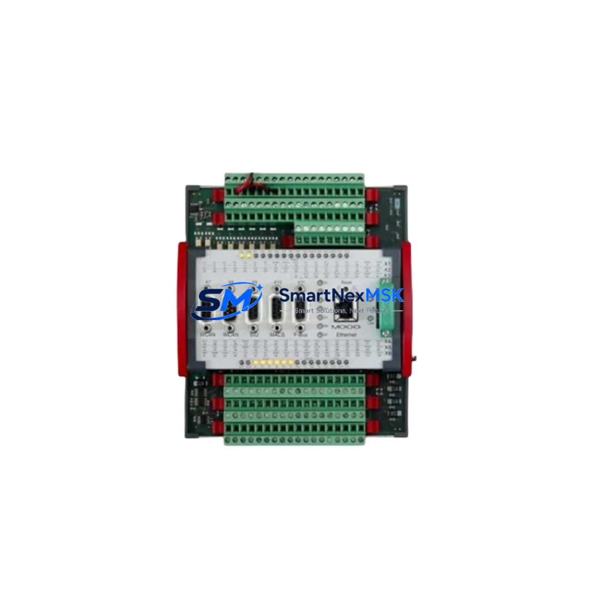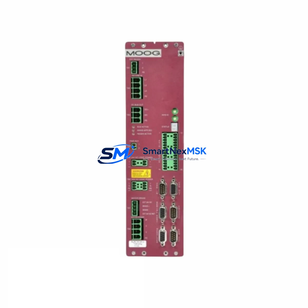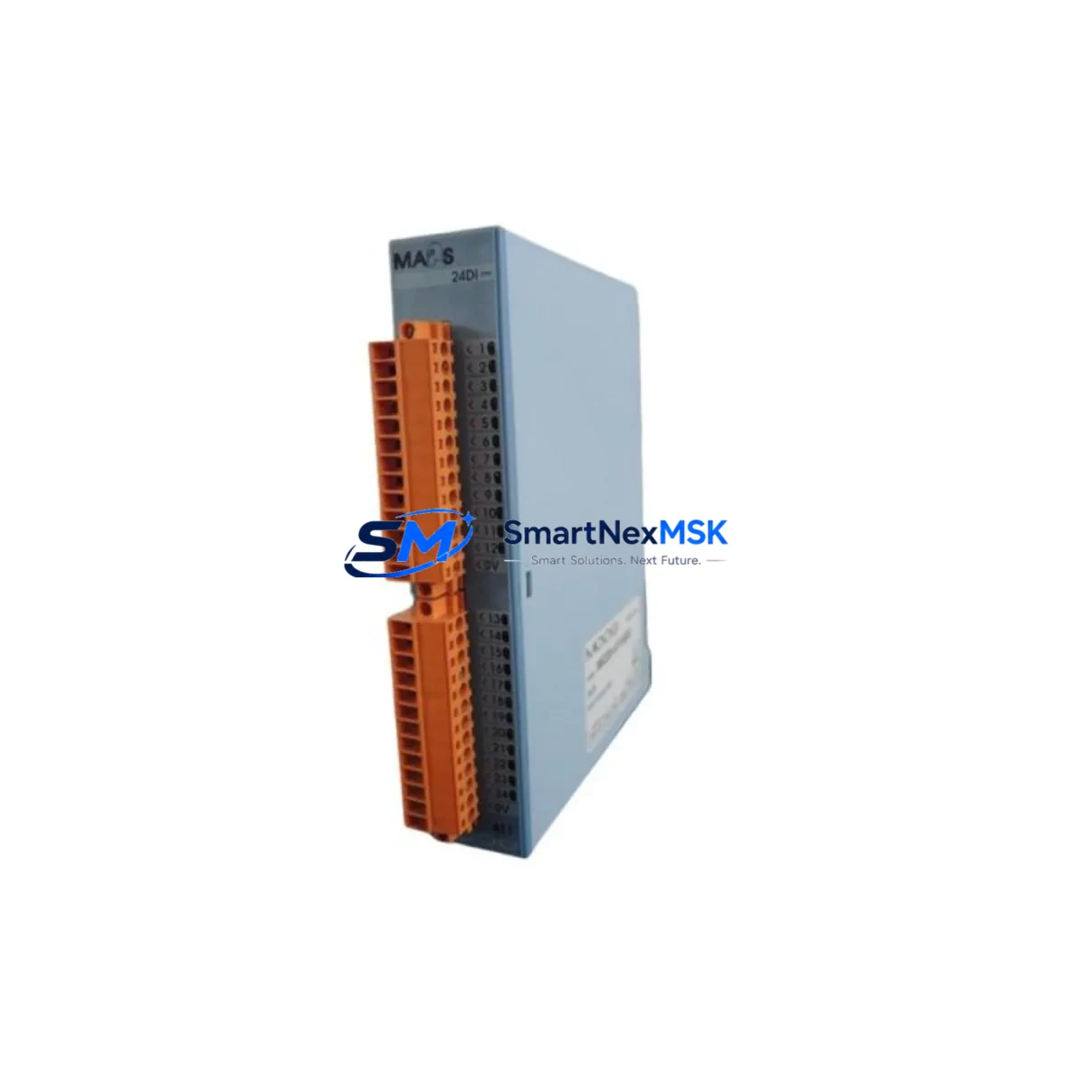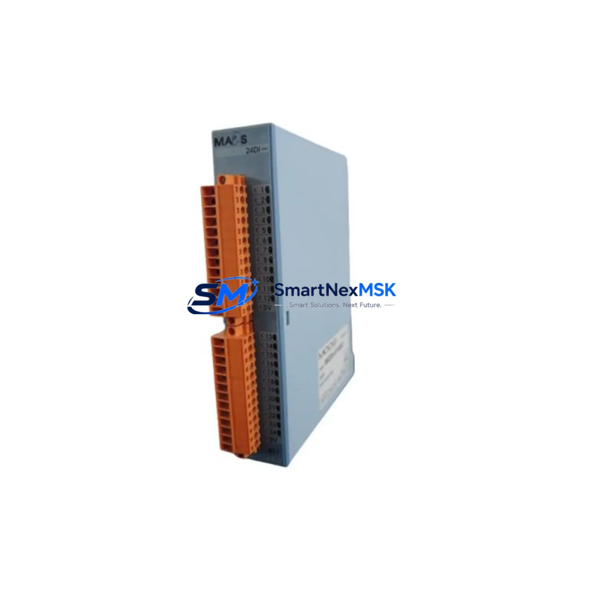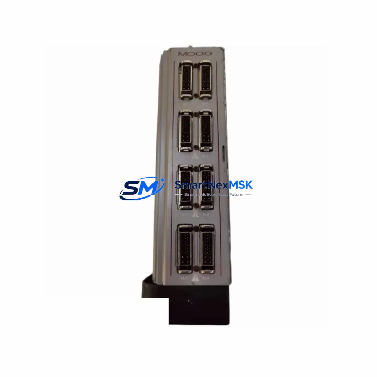
MOOG 110-000-028-03 Maintenance-Ready Spare BX-300A Servo Amplifier
The MOOG 110-000-028-03 is a servo amplifier module from the MOOG BX-300A series, widely deployed in precision motion control systems across CNC machining centers, injection molding machines, industrial robots, and high-performance servo drive platforms. As original equipment ages and OEM support windows close, maintaining a reliable stock of this spare part becomes critical for any maintenance engineer responsible for minimizing unplanned downtime and sustaining production continuity. This unit is sourced as an original spare, fully tested prior to shipment, and backed by a 12-month warranty — making it a dependable choice for both emergency replacement and planned preventive maintenance programs.
When replacing the MOOG 110-000-028-03 in the field, maintenance engineers must verify several key parameters before installation. The BX-300A amplifier operates within a defined DC bus voltage range and requires confirmation that the existing power supply module — often a MOOG T200 series or equivalent regulated DC supply — delivers stable voltage within specification. Any deviation in bus voltage can cause fault codes or damage the replacement unit during commissioning. Engineers should also inspect the feedback cable and encoder interface, as the BX-300A relies on resolver or encoder feedback signals routed through dedicated signal cables; worn or damaged feedback wiring is a common root cause of recurring amplifier faults and must be replaced alongside the amplifier if degradation is detected.
Terminal wiring compatibility is another critical checkpoint. The 110-000-028-03 uses a specific connector pinout for motor phase outputs, enable signals, fault relay contacts, and analog command inputs. Before powering up the replacement unit, technicians should cross-reference the existing wiring diagram against the BX-300A terminal layout to confirm that the ±10V analog command signal, the drive enable input, and the fault output relay are correctly mapped. In systems where the MOOG BX-300A interfaces with a MOOG T161 or T163 motion controller, the axis address DIP switch settings on the amplifier must be configured to match the original module address to avoid axis mapping conflicts in the controller program.
For facilities running MOOG motion controllers such as the MOOG T200 or integrated into a broader multi-axis servo platform, the replacement amplifier must also be verified for firmware compatibility. Some BX-300A variants carry specific firmware revisions that affect tuning parameter ranges and fault behavior. If the system uses a MOOG programming cable and dedicated configuration software, engineers should back up the existing axis parameters — including proportional gain, integral gain, velocity feedforward, and current limits — before swapping the module, and restore them to the replacement unit after installation.
In control cabinet environments, the 110-000-028-03 is typically mounted on a DIN rail or backplane alongside companion modules such as MOOG BX-300A power supply units, regenerative braking resistor modules, and I/O interface cards. During a planned maintenance window, it is good practice to inspect adjacent components including terminal blocks, shielded signal cables, EMC filter modules, and 24VDC control power supplies for signs of wear, overheating, or insulation degradation. Replacing the servo amplifier without addressing deteriorated peripheral components can lead to premature failure of the new unit.
For systems integrated with HMI panels — whether a MOOG-native operator interface or a third-party panel PC running supervisory software — maintenance teams should confirm that the HMI alarm history does not indicate recurring overcurrent, overvoltage, or encoder fault codes that could point to a systemic issue beyond the amplifier itself. Clearing fault logs and verifying HMI communication with the replacement module after commissioning is a standard step in the site replacement workflow.
SMARTNEXMSK maintains inventory of the MOOG 110-000-028-03 and related BX-300A series components to support both emergency procurement and scheduled maintenance programs. All units undergo pre-shipment functional testing and are supplied with documentation confirming test results. With a 12-month warranty and reliable stock availability, this spare part is suitable for inclusion in critical spare parts lists for facilities operating MOOG servo drive systems.
Spare Maintenance Table
| Parameter | Specification / Details |
|---|---|
| Part Number | 110-000-028-03 |
| Series | MOOG BX-300A |
| Product Type | Servo Amplifier |
| Feedback Interface | Resolver / Encoder (series-dependent) |
| Command Input | ±10V Analog / Digital (configuration-dependent) |
| Mounting | DIN Rail / Backplane (BX-300A rack) |
| Application Environment | Industrial control cabinet, CNC, robotics, injection molding |
| Compatibility | MOOG BX-300A series, T200/T161/T163 motion controllers |
| Replacement Recommendation | Direct drop-in replacement for 110-000-028-03; verify DIP switch address and firmware revision |
| Commissioning Notes | Restore axis tuning parameters; verify encoder feedback and bus voltage before enable |
| Warranty | 12-Month Warranty |
| Condition | Original spare, pre-shipment tested |
Maintenance Planning for Continuous Operation
Effective maintenance planning for systems using the MOOG 110-000-028-03 requires a holistic view of the servo drive cabinet. When scheduling a replacement, maintenance engineers should simultaneously inspect the MOOG BX-300A power supply module for output ripple and voltage stability, as a degraded power supply is a leading cause of amplifier failure. The motor feedback cable — typically a shielded multi-conductor cable with resolver or encoder signals — should be tested for continuity and insulation resistance, and replaced if any intermittent faults are detected.
Terminal blocks and wiring ferrules within the control cabinet should be checked for corrosion and loose connections, particularly on the motor phase output terminals and the 24VDC control circuit. EMC filter modules installed on the AC input side of the drive system should be inspected for capacitor degradation. If the system includes a regenerative braking resistor module, its resistance value and thermal condition should be verified to ensure safe deceleration performance after the amplifier replacement.
For multi-axis systems, the MOOG T200 motion controller or equivalent axis controller card should be checked for firmware version compatibility with the replacement amplifier. Communication between the controller and the BX-300A amplifier — whether via analog command signals, serial communication, or fieldbus — should be verified during commissioning. If the system uses a MOOG programming cable for parameter configuration, ensure the cable and software version are available on-site before the maintenance window begins.
Signal isolators used on analog command inputs, safety relay modules in the enable circuit, and 24VDC fuse blocks protecting the control power circuit are all components that should be included in the inspection checklist. Replacing the MOOG 110-000-028-03 as part of a comprehensive cabinet inspection — rather than as a purely reactive swap — significantly reduces the risk of repeat failures and extends the operational life of the overall servo system.
Site Replacement Workflow
The site replacement workflow for the MOOG 110-000-028-03 begins with a controlled shutdown of the affected axis. Before removing the faulty amplifier, the maintenance engineer should document the existing DIP switch settings, record all axis tuning parameters from the motion controller, and photograph the terminal wiring for reference. The DC bus must be fully discharged before any wiring is disturbed — this typically requires a minimum wait time after AC power removal, as specified in the BX-300A service documentation.
After installing the replacement 110-000-028-03, the DIP switch address must be set to match the original configuration. All terminal connections should be re-made according to the wiring photograph and verified against the system wiring diagram. The feedback cable should be reconnected and checked for secure seating at both the amplifier and motor ends. Before enabling the drive, the DC bus voltage should be measured to confirm it is within the specified range for the BX-300A series.
Initial commissioning should be performed with the motor uncoupled from the load where possible, allowing the engineer to verify correct rotation direction, encoder feedback polarity, and basic velocity response before returning the axis to full production load. Axis tuning parameters should be restored from the backup taken before the replacement, and fine-tuned if necessary to account for any differences between the original and replacement unit. Once the axis is confirmed stable under load, the HMI fault log should be cleared and the system returned to normal operation.
Spare Parts Support FAQ
Q: Is the MOOG 110-000-028-03 a direct replacement for all BX-300A variants?
A: The 110-000-028-03 is the primary spare part number for the MOOG BX-300A servo amplifier. However, BX-300A variants may differ in feedback interface type (resolver vs. encoder) and current rating. Always confirm the variant suffix and feedback configuration of the original unit before ordering to ensure full compatibility.
Q: What pre-shipment testing is performed on this spare?
A: Each unit undergoes functional testing prior to shipment, including power-on verification, output stage integrity check, and feedback interface continuity. Test results are documented and available upon request. All units are covered by a 12-month warranty from the date of shipment.
Q: How do I verify compatibility with my existing MOOG motion controller?
A: Compatibility depends on the controller model (e.g., MOOG T161, T163, or T200 series) and the communication interface used. Provide your controller model and axis configuration details when placing your order, and our technical team will confirm compatibility before shipment.
Q: What is the lead time and warranty coverage?
A: In-stock units are dispatched within 1–3 business days. The 12-month warranty covers manufacturing defects and functional failures under normal operating conditions. Warranty claims are supported with replacement or repair, subject to inspection of the returned unit.
© 2026 SMARTNEXMSK. All rights reserved.
Original Source: https://smartnexmsk.com
Contact: [email protected] | +86 18259474341