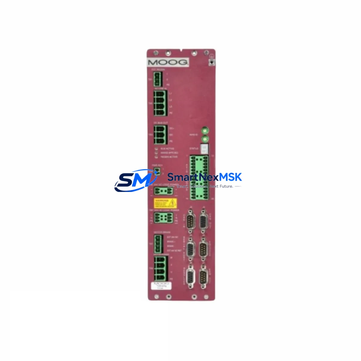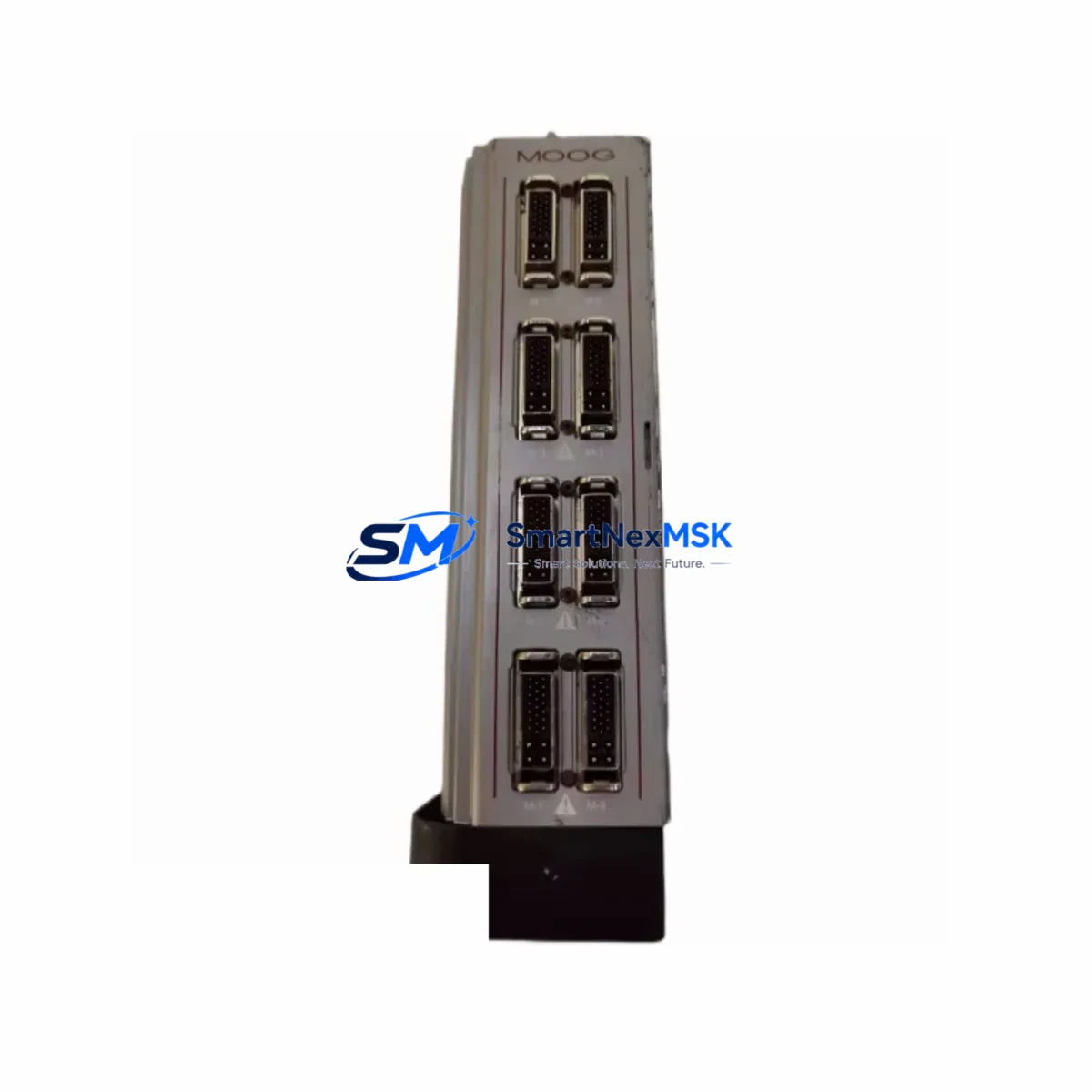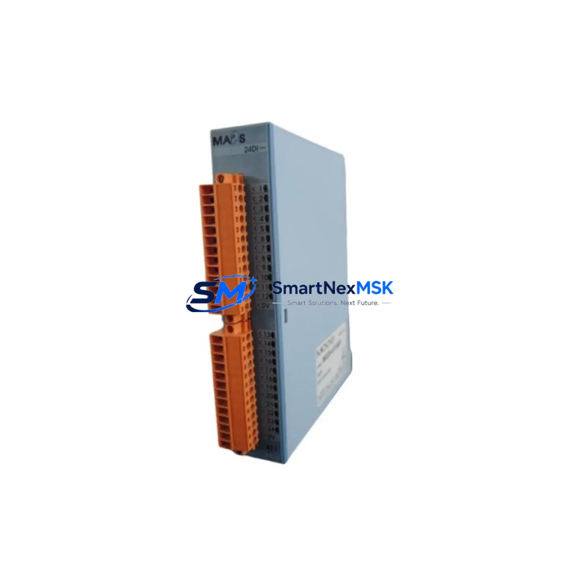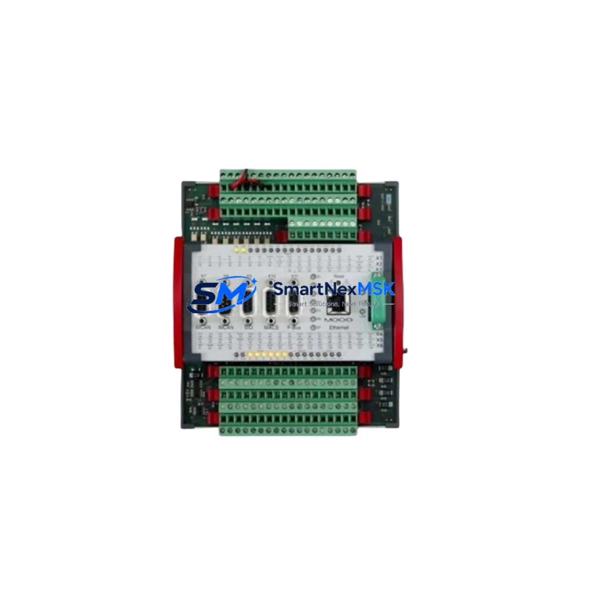
MOOG D136-002-005 Maintenance-Ready Spare for D136 Series Automation
The MOOG D136-002-005 is a precision servo controller designed for demanding industrial automation environments. As a maintenance-ready spare, it enables maintenance and procurement engineers to execute rapid in-situ replacement, restore machine availability, and eliminate extended unplanned downtime in servo-driven production lines, CNC machining centers, and closed-loop motion control systems. Whether you are managing a planned shutdown, responding to an emergency fault, or building a strategic spare parts buffer, the D136-002-005 delivers the original MOOG performance specification your system was commissioned with.
Sourced directly from authorized supply channels, every unit undergoes pre-shipment functional verification covering power-on self-test, analog command signal response, enable/disable logic, and fault output integrity. The result is a component that arrives ready for installation — not just ready for the shelf.
Spare Maintenance Table
| Parameter | Specification / Detail |
|---|---|
| Part Number | D136-002-005 |
| Brand | MOOG |
| Series | D136 Servo Controller Series |
| Product Type | Servo Controller / Drive Amplifier |
| Origin | USA (Original MOOG manufacture) |
| Compatibility | Drop-in replacement for D136-002-005; compatible with MOOG D136 Series servo drive systems |
| Application Environment | Industrial automation, CNC, hydraulic servo systems, closed-loop motion control |
| Installation | Panel-mount; refer to MOOG D136 Series installation manual for wiring and parameter configuration |
| Pre-shipment Testing | Power-on self-test, command signal response, enable logic, fault output verification |
| Condition | Original / New or Refurbished-to-OEM-spec (confirmed at order) |
| Warranty | 12 Months from date of shipment |
| Lead Time | In-stock units ship within 1–3 business days; contact for availability |
| Maintenance Recommendation | Inspect mating connectors, feedback cable shielding, and power supply rails at replacement interval |
Maintenance Planning for Continuous Operation
A servo controller replacement is rarely an isolated event. When a MOOG D136-002-005 is flagged for replacement — whether due to a fault code, thermal event, or scheduled life-cycle swap — the surrounding electrical circuit deserves equal scrutiny. Experienced maintenance engineers treat the controller swap as an opportunity to audit the entire servo loop.
Begin with the DC bus power supply feeding the D136 amplifier. Voltage ripple, capacitor degradation, or an undersized supply rail can stress a new controller within weeks of installation. Verify that the supply output is within the D136 Series rated input tolerance before energizing the replacement unit. Alongside the power supply, inspect the 24 VDC logic supply and its associated fusing — a blown or marginal fuse is a common silent contributor to intermittent servo faults.
Next, examine the resolver or encoder feedback cable and its connector. Damaged shielding or a loose pin at the D-sub feedback connector is a leading cause of position error faults that are incorrectly attributed to the controller itself. If the machine uses a MOOG D661 or D633 Series proportional valve amplifier in the same hydraulic servo circuit, inspect its command input wiring simultaneously — shared signal ground issues can manifest as erratic behavior after a controller swap.
For systems integrated into a broader PLC or DCS architecture, verify the analog command signal (typically ±10 V) from the motion controller output card. A degraded analog output module on the PLC rack — such as a Siemens SM 332 or Allen-Bradley 1756-OF8 — can deliver a noisy or offset command that prevents the new D136-002-005 from tuning correctly. Use a calibrated multimeter or oscilloscope to confirm signal quality before closing the loop.
The enable relay and its associated wiring in the safety circuit should be tested for contact resistance and correct sequencing. A worn relay contact that intermittently drops the enable signal will generate nuisance faults on the new controller. Similarly, inspect any signal isolators in the command or feedback path — isolation barriers degrade over time and can introduce offset or bandwidth limitations that affect servo performance.
If the machine cabinet houses a MOOG D136 Series companion axis or a secondary servo amplifier sharing the same DC bus, check that unit’s health indicators as well. A failing neighbor on a shared bus can cause voltage transients that damage a newly installed controller. Finally, review the terminal blocks and DIN rail wiring in the servo drive section of the cabinet — loose terminations are a disproportionate source of intermittent faults in high-vibration environments.
Building a structured spare parts kit around the D136-002-005 — including a spare feedback cable assembly, a set of rated fuses, a backup enable relay, and a tested analog output module — reduces mean time to repair (MTTR) from hours to minutes on future incidents.
Site Replacement Workflow
Step 1 — Fault Isolation: Confirm the D136-002-005 is the root cause before removal. Check the fault code on the machine HMI or operator panel. Document the active fault, axis number, and any recent alarm history. If the system uses a MOOG Axis Controller or third-party motion controller with diagnostic logging, export the fault log before power-down.
Step 2 — Safe Isolation: Follow site LOTO (Lockout/Tagout) procedures. Isolate the DC bus, discharge bus capacitors per the MOOG D136 Series safety guidelines, and verify zero voltage with a calibrated meter before touching any wiring.
Step 3 — Document and Disconnect: Photograph all connector positions and cable routing before disconnection. Label each connector if not already marked. Note any DIP switch or potentiometer settings on the outgoing unit — these must be replicated on the replacement D136-002-005.
Step 4 — Install Replacement: Mount the D136-002-005 in the original panel position. Reconnect all connectors in reverse order of removal. Replicate DIP switch and gain potentiometer settings from your documentation. Verify that the feedback cable shield is grounded at one end only, per MOOG wiring guidelines.
Step 5 — Power-On and Verification: Restore power in sequence — logic supply first, then DC bus. Monitor the fault indicator on the D136-002-005 during power-on. Command a slow jog move and verify smooth, fault-free response before returning the axis to automatic mode. Log the replacement date, unit serial number, and test results in the machine maintenance record.
This workflow is compatible with both like-for-like replacement of a failed D136-002-005 and planned life-cycle swap of an aging unit that has accumulated hours beyond its recommended service interval. Proactive replacement before failure eliminates unplanned downtime and protects the broader servo system from secondary damage caused by a failing controller.
Spare Parts Support FAQ
Q1: Is the D136-002-005 a direct drop-in replacement for the original MOOG unit?
Yes. The D136-002-005 is supplied to the original MOOG specification and is a direct mechanical and electrical replacement. No firmware changes or parameter re-commissioning are required beyond replicating the DIP switch and potentiometer settings from the outgoing unit. Confirm your exact machine revision with our technical team if you are replacing a unit manufactured before 2010, as minor hardware revisions may apply.
Q2: What pre-shipment testing is performed on each unit?
Every D136-002-005 shipped by SMARTNEXMSK undergoes a structured pre-shipment test covering power-on self-test, analog command signal response across the full ±10 V range, enable/disable logic sequencing, and fault output verification. A test record is available on request. Units are packed in anti-static packaging with mechanical protection for safe transit.
Q3: What does the 12-month warranty cover?
The 12-month warranty covers manufacturing defects and functional failures under normal operating conditions from the date of shipment. It does not cover damage resulting from incorrect installation, overvoltage events, or operation outside the rated environmental specifications. In the event of a warranty claim, SMARTNEXMSK provides advance replacement to minimize your downtime, subject to stock availability.
Q4: Can you support long-term supply for legacy D136 Series systems?
Yes. SMARTNEXMSK maintains ongoing sourcing relationships for MOOG D136 Series components to support customers operating legacy systems beyond the OEM’s active production period. We recommend establishing a blanket order or consignment stock arrangement if your facility operates multiple D136-equipped machines. Contact our team to discuss volume pricing, reserved stock agreements, and multi-year supply planning.
© 2026 SMARTNEXMSK. All rights reserved.
Original Source: https://smartnexmsk.com
Contact: [email protected] | +86 18259474341