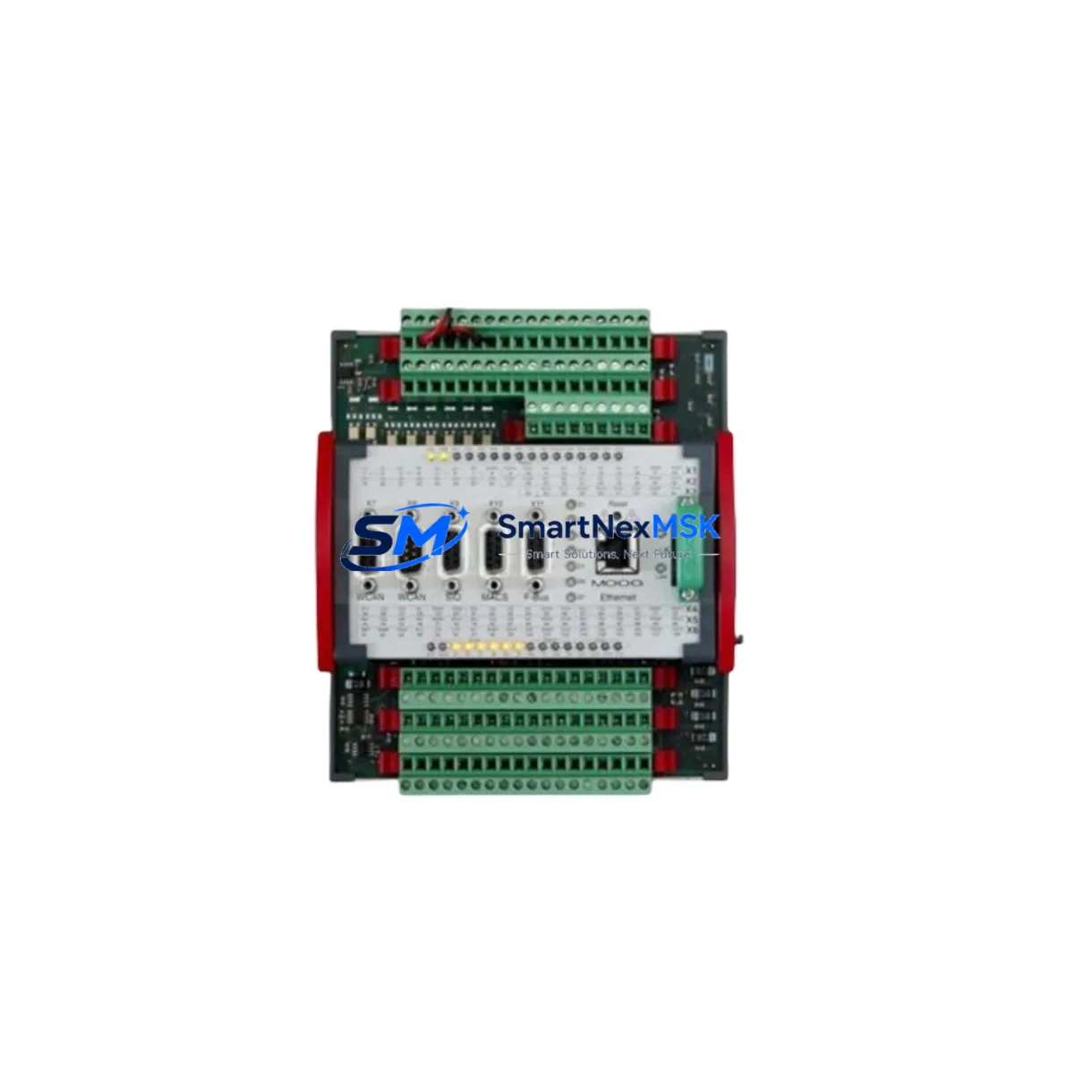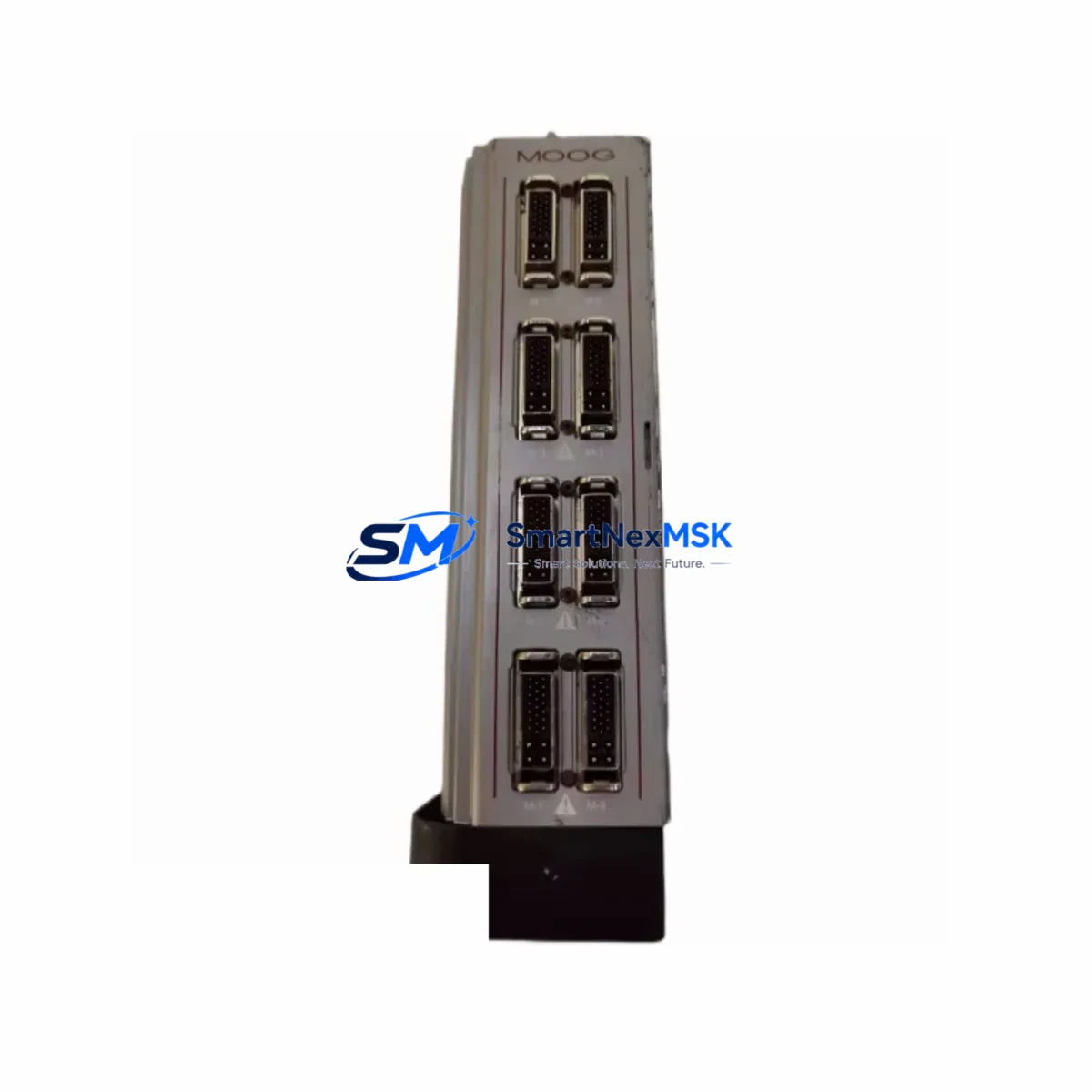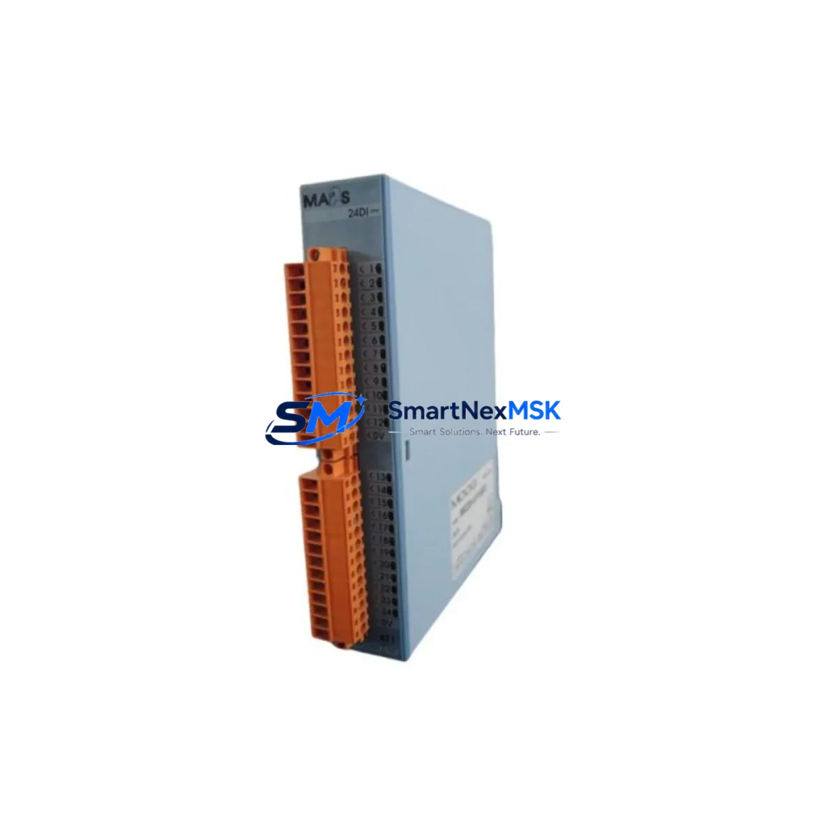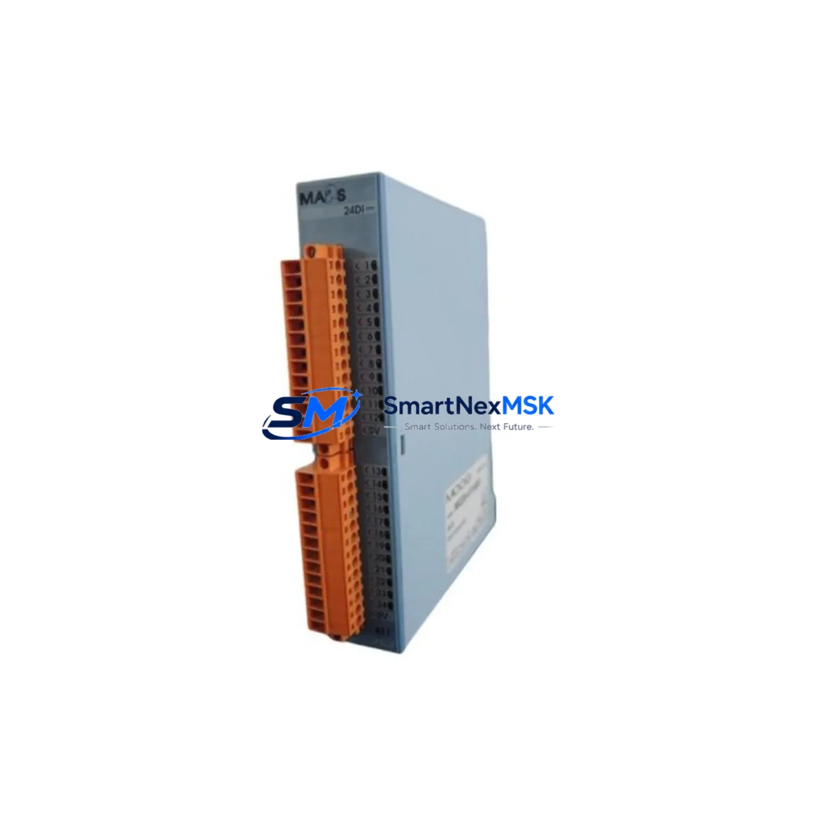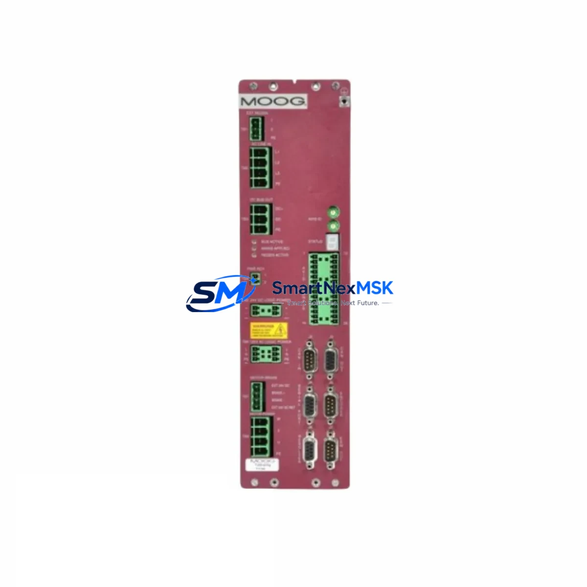
MOOG G392-024-020-001 Maintenance-Ready Spare for G392 Servo Automation
When a servo amplifier fails on a precision motion control line, every minute of downtime translates directly into lost production and escalating recovery costs. The MOOG G392-024-020-001 is an original brushless AC servo amplifier from MOOG’s proven G392 Series, engineered for demanding industrial automation environments where motion accuracy, loop stability, and continuous duty reliability are non-negotiable. Whether you are managing a planned maintenance window, responding to an unscheduled fault, or building a strategic spare parts inventory for a critical servo axis, the G392-024-020-001 delivers a direct, tested replacement that restores full system performance without the risk of compatibility compromise.
Maintenance engineers working on MOOG-driven systems understand that the servo amplifier sits at the heart of the motion control loop. It receives velocity and torque commands from the motion controller, conditions power delivery to the servo motor, and closes the feedback loop through encoder or resolver signals. A degraded or failed G392-024-020-001 can manifest as axis following errors, velocity instability, overcurrent faults, or complete axis loss — all of which halt production. Having a verified original spare on the shelf eliminates the diagnostic uncertainty that comes with sourcing unverified aftermarket alternatives.
Spare Maintenance Table
| Parameter | Specification |
|---|---|
| Manufacturer | MOOG |
| Part Number / SKU | G392-024-020-001 |
| Series | G392 Series |
| Product Type | Brushless AC Servo Amplifier |
| Rated Output Current | 20 A continuous / 40 A peak (typical G392-024-020 rating) |
| Supply Voltage | 3-phase 200–240 VAC, 50/60 Hz |
| Feedback Interface | Encoder / Resolver compatible (G392 standard) |
| Command Interface | Analog ±10 V / Digital step-direction / Fieldbus (application dependent) |
| Operating Temperature | 0 °C to +45 °C (ambient, with adequate cabinet ventilation) |
| Storage Temperature | -25 °C to +70 °C |
| Protection Class | IP20 (panel-mount, control cabinet installation) |
| Cooling Method | Forced air / heatsink (internal fan) |
| Origin | Germany |
| Compatibility | Direct replacement for G392-024-020-001; compatible with MOOG G392 series servo motors and motion controllers |
| Condition | Original, new or refurbished-to-spec; fully tested before shipment |
| Warranty | 12-Month Warranty — covers manufacturing defects and functional failure under normal operating conditions |
Maintenance Planning for Continuous Operation
Replacing a MOOG G392-024-020-001 in the field is rarely an isolated task. Experienced maintenance engineers know that a servo amplifier fault is often a symptom of broader stress in the drive cabinet, and a thorough inspection of surrounding components during the replacement window can prevent repeat failures and extend mean time between maintenance events.
Before reinstalling a new G392-024-020-001, inspect the DC bus capacitor bank and the regenerative braking resistor — both are common wear items in high-cycle servo applications. Verify that the 24 VDC control power supply feeding the amplifier’s logic board is within tolerance; a sagging control rail is a frequent but overlooked cause of amplifier faults. Check the motor power cable and feedback cable for insulation damage, connector pin corrosion, and shield continuity — degraded cables introduce noise into the resolver or encoder signal that can destabilize the velocity loop even after a new amplifier is installed.
On the motion controller side, confirm that the MOOG motion controller (such as a T200 or compatible axis board) has its firmware and axis parameters backed up before the swap. Re-tuning the servo loop after a hardware replacement is standard practice, and having the original gain parameters on record shortens commissioning time significantly. If the system uses a MOOG D136 or D137 series drive on adjacent axes, inspect those units for similar thermal stress indicators — capacitor bulging, discolored PCB traces, or intermittent enable faults — while the cabinet is open.
The encoder or resolver feedback module should be tested independently if the previous amplifier failed with a feedback fault code. A faulty resolver-to-digital converter or a damaged encoder line driver can destroy a replacement amplifier within hours if not identified beforehand. Similarly, check the I/O terminal strip and safety relay wiring for the drive enable, fault reset, and hardware limit switch signals — loose terminals in these circuits cause nuisance faults that are difficult to diagnose after reassembly.
For systems with fieldbus communication (CANopen, PROFIBUS, or EtherCAT), verify that the fieldbus node address and baud rate settings on the replacement amplifier match the original configuration. Some G392 variants store these parameters in non-volatile memory on the amplifier itself, so a factory-fresh unit will require parameter download from the engineering workstation before the axis can be enabled. Keep a copy of the axis configuration file in the maintenance documentation folder alongside the spare part record.
Finally, review the cabinet thermal management: clean or replace the cabinet door filter mats, verify that the cooling fan on the amplifier heatsink spins freely, and confirm that cable routing does not obstruct airflow across the drive stack. Overtemperature is the leading cause of premature servo amplifier failure in continuous-production environments, and addressing it during a planned replacement extends the service life of the new G392-024-020-001 considerably.
Site Replacement Workflow
A structured replacement workflow minimizes downtime and reduces the risk of commissioning errors when swapping a MOOG G392-024-020-001 in a live production environment.
Step 1 — Fault Documentation: Before powering down, record all active fault codes from the drive display or the motion controller diagnostic screen. Photograph the existing wiring, terminal assignments, and DIP switch or parameter settings on the outgoing amplifier. This documentation is essential if the replacement unit requires manual parameter entry.
Step 2 — Safe Isolation: Follow your site’s lockout/tagout procedure. Isolate the three-phase AC supply and the 24 VDC control power. Allow the DC bus capacitors to discharge fully — typically 5 minutes after power removal — before touching any internal connections. Verify zero voltage with a calibrated meter before proceeding.
Step 3 — Mechanical Removal: Disconnect the motor power connector (U/V/W), the feedback cable, the control I/O connector, and the fieldbus connector in sequence. Label each connector if they are not already keyed or color-coded. Remove the amplifier from the DIN rail or panel mount, noting the torque values for any captive screws.
Step 4 — Inspection and Preparation: Inspect the mounting surface and connector backshells for damage. Clean the heatsink contact surface if thermal compound is used. Verify that the replacement G392-024-020-001 has the correct firmware version for your application — check the label or query the unit via the commissioning software before installation.
Step 5 — Installation and Parameter Restore: Mount the new amplifier, reconnect all cables in reverse order, and restore the axis parameters from the backup file. Set the node address and any hardware configuration switches to match the original. Power up the control supply first and confirm that the drive enters the expected idle state before applying the three-phase supply.
Step 6 — Commissioning and Test: Enable the axis under no-load conditions and verify encoder or resolver feedback signal quality. Run a slow jog move in both directions to confirm correct motor phasing and feedback polarity. Restore normal operating speed and load, monitor the drive temperature and current draw for the first 30 minutes of operation, and log the results in the maintenance record.
This workflow applies equally to planned preventive replacements and emergency corrective maintenance, and it is compatible with MOOG’s recommended service procedures for the G392 series.
Spare Parts Support FAQ
Q1: What does the 12-month warranty cover for the MOOG G392-024-020-001?
The 12-month warranty covers manufacturing defects and functional failure under normal operating and storage conditions from the date of shipment. Each unit undergoes functional testing prior to dispatch, including power-on verification, output stage integrity check, and feedback interface validation. If a unit fails within the warranty period under normal use, we provide a replacement or full refund. The warranty does not cover damage caused by incorrect installation, overvoltage events, or mechanical impact.
Q2: How do I confirm compatibility before ordering?
The G392-024-020-001 is a direct part-number replacement within the MOOG G392 series. Compatibility is confirmed by matching the full part number on the nameplate of the outgoing unit. If your existing amplifier carries a different suffix variant (e.g., -002 or -003), contact our technical team with the full nameplate data and motor specifications — we will verify interchangeability and advise on any parameter adjustments required. We support compatibility verification for all major MOOG servo drive families.
Q3: Is long-term supply availability guaranteed for this part?
We maintain dedicated stock of MOOG G392 series components to support customers with legacy systems and long production lifecycles. Our procurement strategy prioritizes original manufacturer stock and verified refurbished-to-spec units to ensure consistent supply even for discontinued or end-of-life part numbers. Customers managing multi-year maintenance contracts are encouraged to discuss volume reservation arrangements with our sales team to lock in availability and pricing.
Q4: What pre-shipment testing is performed on each unit?
Every MOOG G392-024-020-001 shipped from our facility undergoes a standardized pre-shipment inspection that includes visual inspection for physical damage, power-on functional test, output stage load test, feedback interface signal verification, and parameter memory integrity check. Units that do not pass all test criteria are quarantined and not shipped. A test record is available upon request and can be included with the shipment documentation for traceability purposes.
© 2026 SMARTNEXMSK. All rights reserved.
Original Source: https://smartnexmsk.com
Contact: [email protected] | +86 18259474341