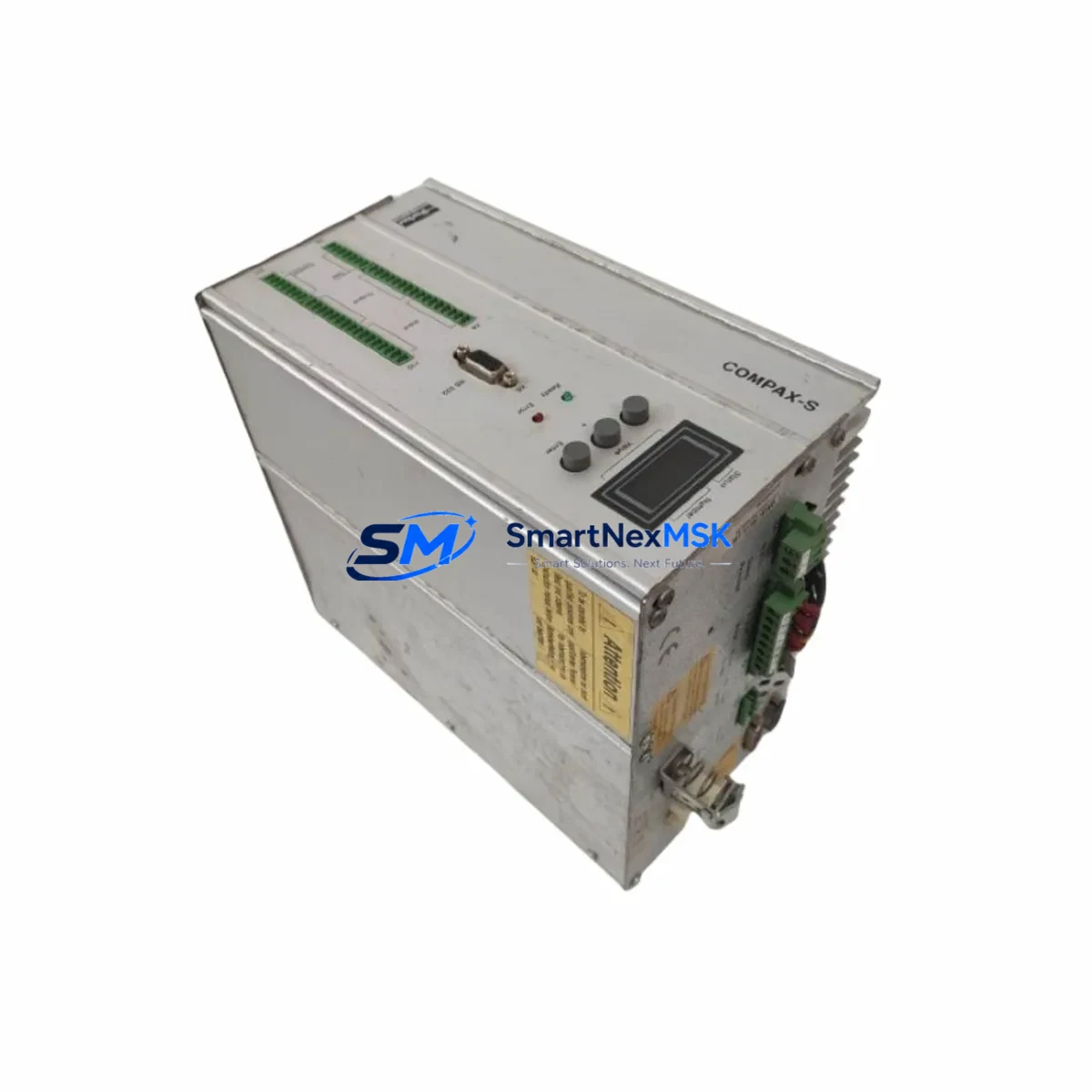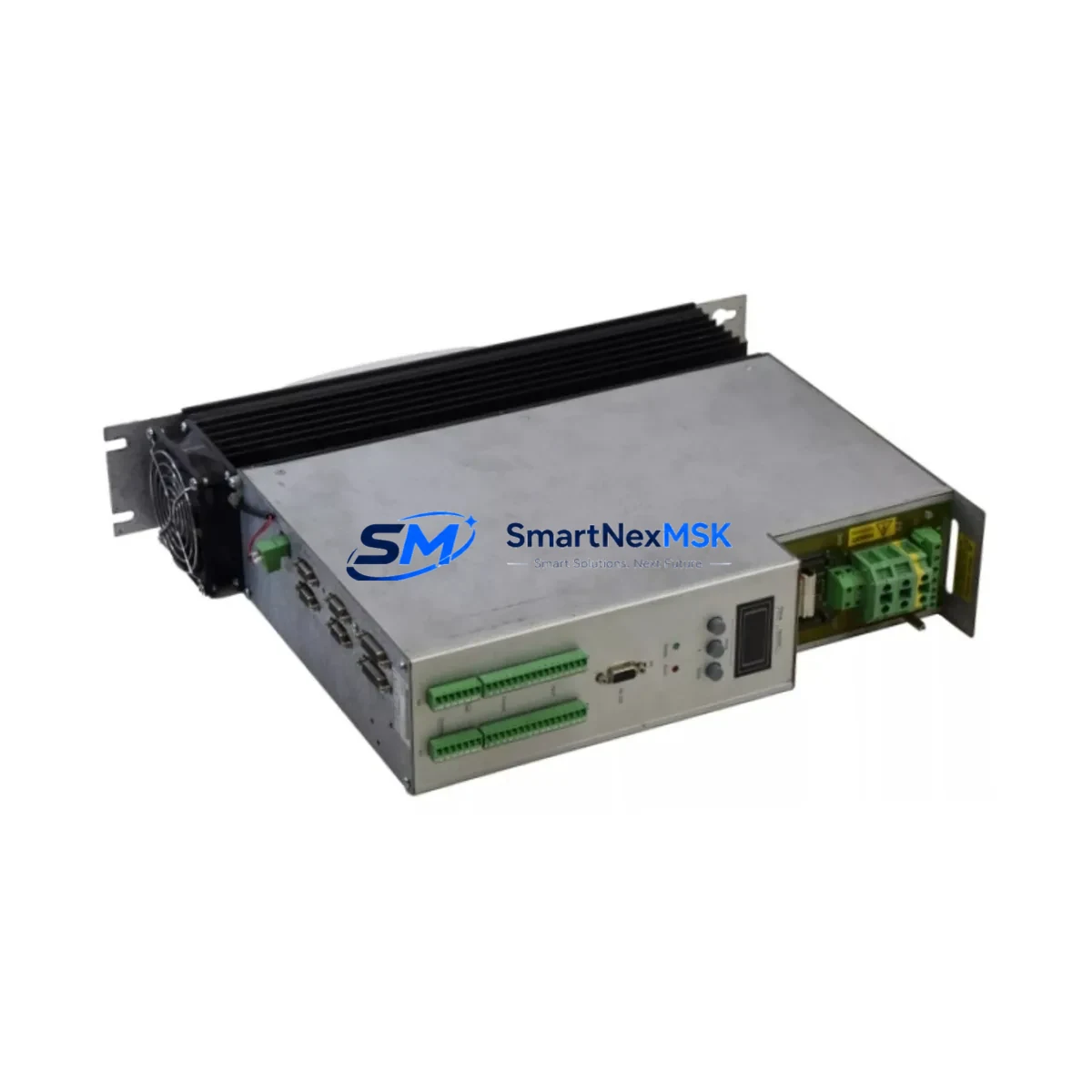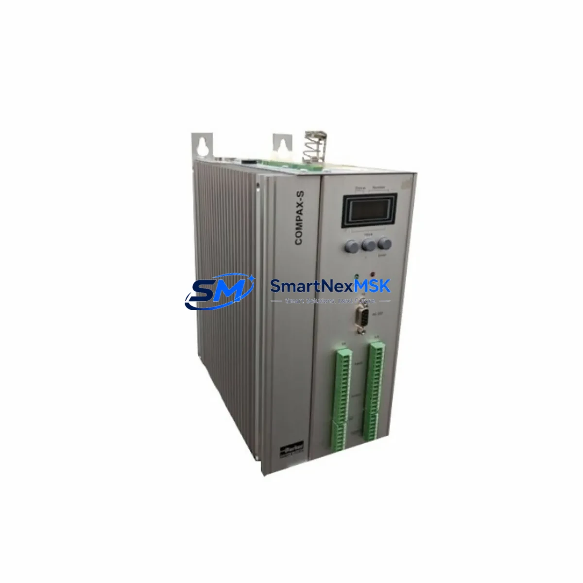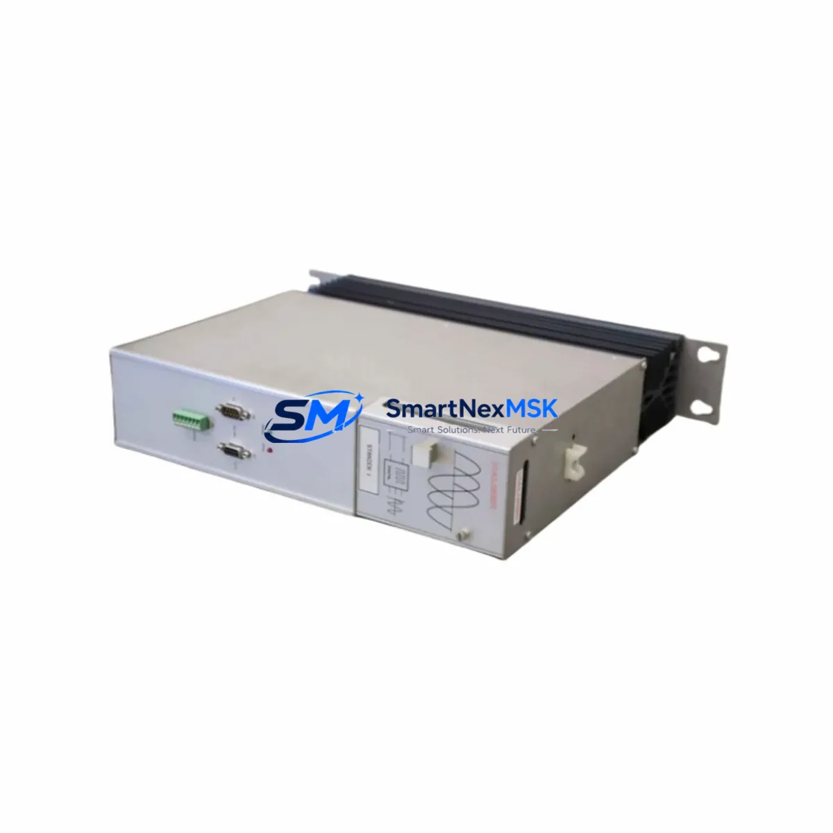
Parker 951-300000 Maintenance-Ready Spare for Compax Automation
The Parker 951-300000 is an original AC/DC industrial power supply module engineered for the Parker Hauser Compax servo drive series. In industrial automation environments where unplanned downtime translates directly into production loss, having a verified, maintenance-ready spare of the 951-300000 on hand is a fundamental element of any responsible spare parts strategy. This unit is sourced as an original Parker Hannifin component, fully tested prior to shipment, and backed by a 12-month warranty — making it a reliable choice for both planned maintenance cycles and emergency breakdown recovery.
Maintenance engineers and procurement teams working with Compax-based motion control systems will recognize the 951-300000 as a critical power supply node within the drive cabinet. Its failure can immediately halt servo axis operation, triggering E-stop conditions across the entire machine cell. Rapid replacement with a pre-verified spare is the fastest path to restoring normal operation without waiting for OEM lead times that can stretch weeks or months for legacy components.
Spare Maintenance Table
| Parameter | Specification / Detail |
|---|---|
| Part Number / SKU | 951-300000 |
| Brand | Parker Hannifin (Hauser) |
| Series Compatibility | Parker Hauser Compax Servo Drive Series |
| Product Type | Industrial AC/DC Power Supply Module |
| Origin | Germany (DE) |
| Application | Servo drive cabinet power supply, motion control systems, industrial automation |
| Installation | DIN rail / panel mount, cabinet-integrated |
| Operating Environment | Industrial control cabinet, IP20 internal environment |
| Compatibility Verification | Cross-referenced against Compax series drive documentation prior to shipment |
| Pre-Shipment Testing | Functional power-on test, output voltage verification |
| Warranty | 12 Months from date of shipment |
| Supply Condition | Original Parker Hannifin component, long-term stock available |
| Lead Time | In stock — typically ships within 1–3 business days |
Maintenance Planning for Continuous Operation
When a 951-300000 power supply failure is identified during routine control cabinet inspection or fault diagnosis, experienced maintenance engineers know that the power supply rarely fails in isolation. A thorough site assessment should accompany any power supply replacement to prevent repeat failures and ensure the restored system operates reliably through the next planned maintenance window.
Begin by inspecting the Compax servo drive module itself — the drive’s internal DC bus capacitors and gate driver circuits are directly dependent on stable input power, and a degraded 951-300000 may have subjected the drive to undervoltage stress over time. Check the 24VDC auxiliary power rail that feeds the Compax control board; a dedicated 24V SMPS module supplying logic power should be verified for output stability before the new power supply is commissioned.
Examine the terminal blocks and wiring harnesses connected to the 951-300000’s AC input and DC output terminals. Loose or corroded terminal connections are a common root cause of intermittent power supply faults in high-vibration industrial environments. Replace any suspect terminal blocks from the same cabinet rail to maintain consistent contact quality. Inspect the input fuse or circuit breaker protecting the 951-300000’s AC feed — a blown fuse may indicate an upstream fault that must be resolved before the replacement unit is energized.
For Compax systems integrated with a PLC — whether a Siemens S7-300, Allen-Bradley ControlLogix, or similar platform — verify that the PLC’s I/O modules and communication interface cards are receiving stable power after the replacement. The Compax drive communicates with the PLC via RS-232, RS-485, or CANopen depending on the system configuration; confirm that the communication module or fieldbus adapter is functioning correctly after power restoration. If the cabinet includes a signal isolator or analog output module for speed or torque reference signals, test the signal integrity before returning the axis to automatic mode.
Relay output modules and safety relays within the same cabinet should be inspected for contact wear, particularly the enable relay and the STO (Safe Torque Off) circuit relay, as these components experience switching stress during every drive fault and reset cycle. An HMI panel connected to the Compax system should be checked for alarm history — reviewing the fault log before clearing errors can reveal whether the power supply failure was preceded by overcurrent, overtemperature, or communication fault events that point to a broader system issue.
Maintaining a minimum stock of one 951-300000 unit per Compax-equipped machine cell is a widely adopted practice among maintenance teams managing legacy Parker Hauser installations. For facilities operating multiple Compax axes, a consolidated spare parts kit covering the power supply, the drive module, key I/O cards, and communication adapters provides the fastest possible recovery path for any single-point failure scenario.
Site Replacement Workflow
Before beginning the replacement of the 951-300000, isolate the control cabinet from mains power and follow your site’s lockout/tagout procedure. Allow sufficient discharge time for any internal capacitors in the Compax drive before handling internal components. Document the existing wiring configuration with photographs or a wiring diagram reference before disconnecting any terminals from the old power supply unit.
Remove the faulty 951-300000 by releasing its mounting hardware and carefully disconnecting the AC input and DC output terminal connections. Install the replacement unit in the same mechanical position, reconnect all terminals according to the documented wiring configuration, and verify torque on all terminal screws. Before restoring mains power, perform a continuity check on the AC input circuit and confirm that the output terminals are not short-circuited.
Restore power and measure the DC output voltage at the 951-300000’s output terminals before connecting the Compax drive load. Confirm the output is within the specified tolerance. Reconnect the drive load, restore the 24VDC auxiliary supply, and power up the Compax drive. Clear any stored fault codes via the drive’s parameter interface or the connected HMI, and perform a controlled jog test on the affected axis before returning the machine to production. Log the replacement in your maintenance management system with the date, the replaced part number, and the failure mode observed.
This workflow minimizes total downtime by ensuring that the replacement unit is verified at each stage before the system is returned to automatic operation — a critical discipline when working with servo-driven production equipment where an undetected wiring error can cause immediate re-failure or mechanical damage.
Spare Parts Support FAQ
Q: Is the 951-300000 compatible with all variants of the Parker Hauser Compax series?
A: The 951-300000 is the standard power supply module for the Parker Hauser Compax servo drive family. Compatibility should be confirmed against your specific Compax drive model number and revision. Our technical team can cross-reference your drive’s nameplate data against the 951-300000 specification prior to shipment upon request.
Q: What pre-shipment testing is performed on the 951-300000?
A: Each 951-300000 unit undergoes a functional power-on test and output voltage verification before dispatch. Units are inspected for physical condition and packaged to prevent transit damage. A test report is available upon request for quality-critical procurement processes.
Q: How should the 951-300000 be stored as a long-term cabinet spare?
A: Store the unit in its original anti-static packaging in a dry, temperature-controlled environment away from direct sunlight and corrosive atmospheres. Recommended storage temperature is 0–40°C with relative humidity below 85% non-condensing. Inspect the unit annually and rotate stock to ensure the oldest unit is used first.
Q: What does the 12-month warranty cover?
A: The 12-month warranty covers manufacturing defects and functional failure under normal operating conditions from the date of shipment. It does not cover damage resulting from incorrect installation, overvoltage events, or operation outside the specified environmental conditions. Warranty claims are supported with a replacement unit or full refund at our discretion.
© 2026 SMARTNEXMSK. All rights reserved.
Original Source: https://smartnexmsk.com
Contact: [email protected] | +86 18259474341