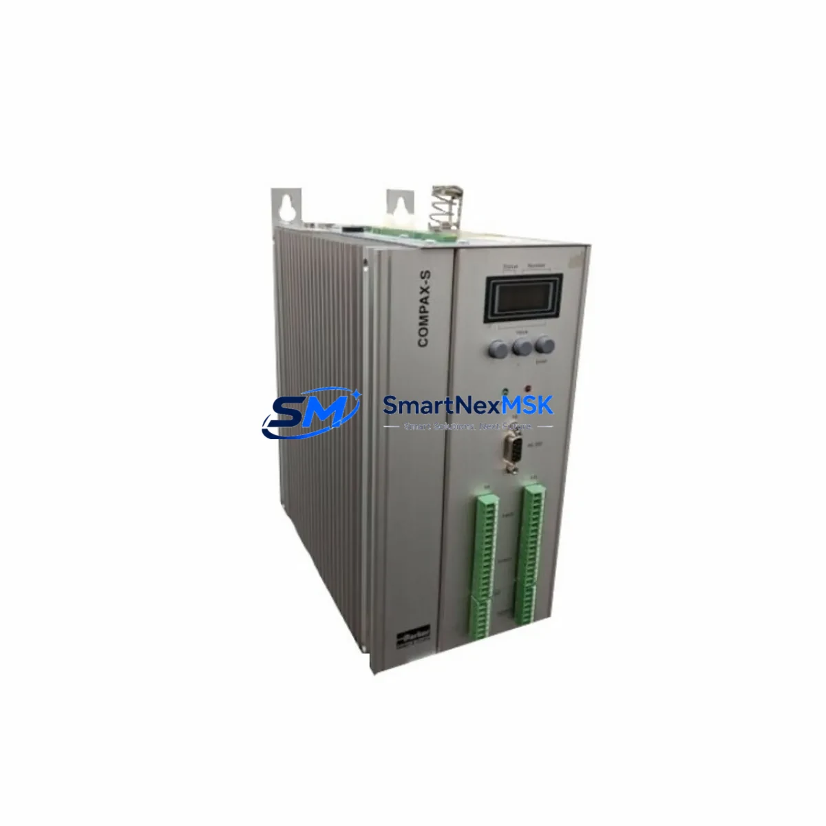
Parker CPX2570S/E2/F3 Retrofit-Ready Digital Servo Drive for Compax-S Control Systems
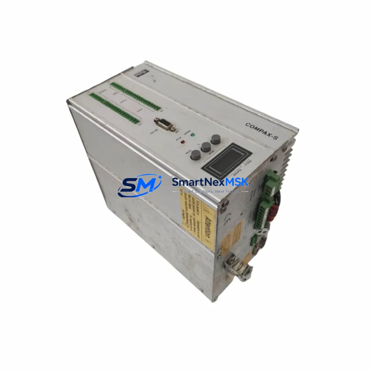
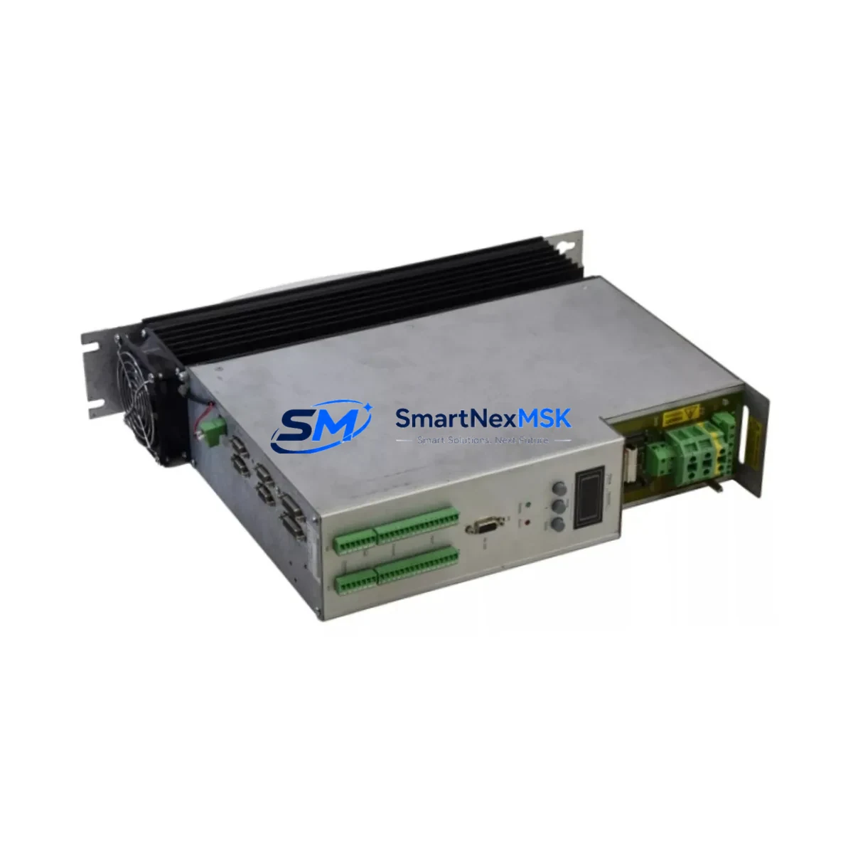
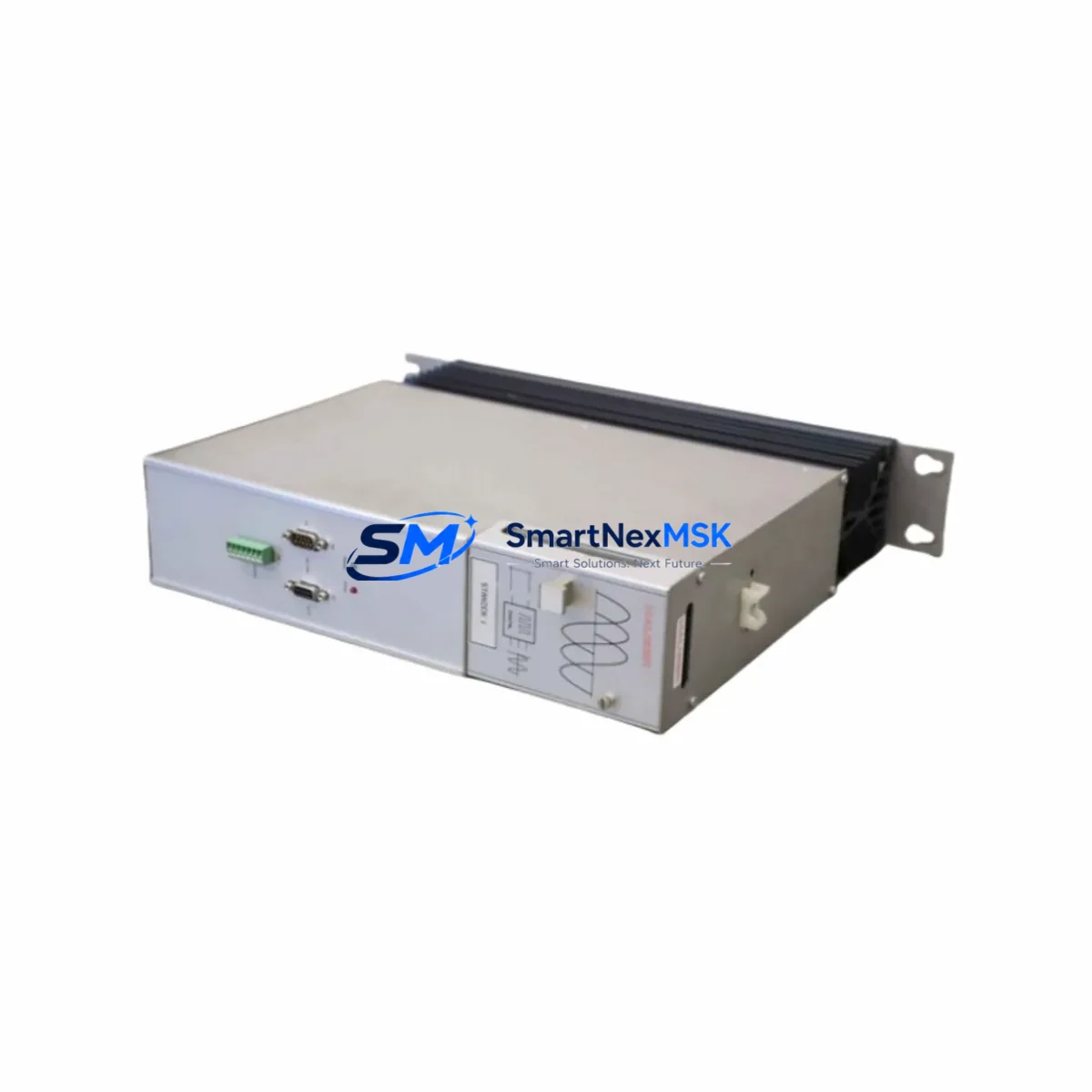
The Parker CPX2570S/E2/F3 is a high-performance digital servo drive from Parker Hannifin’s Compax-S series, engineered for demanding motion control applications in industrial automation. With a continuous current rating of 25A and a peak output of 70A, this drive delivers precise torque and velocity control across a wide range of servo motor configurations. The E2 feedback interface supports Resolver-based motor feedback, while the F3 fieldbus option enables seamless EtherCAT communication — making this unit a direct retrofit candidate for legacy Compax-S installations that require modern fieldbus integration without full system redesign.
For facilities operating aging Parker Compax-S control cabinets, the CPX2570S/E2/F3 represents a validated upgrade path that preserves existing wiring infrastructure, motor cabling, and — in most cases — the original IEC 61131-3 motion program logic. Whether you are replacing a failed unit, upgrading from an earlier Compax-S variant, or migrating a multi-axis gantry system to EtherCAT topology, this drive is stocked and ready for immediate dispatch with a 12-month warranty.
Upgrade Compatibility Table
| Parameter | CPX2570S/E2/F3 Specification | Retrofit Notes |
|---|---|---|
| Continuous / Peak Current | 25A / 70A | Verify motor nameplate current does not exceed 25A RMS continuous |
| Feedback Interface (E2) | Resolver (2-pole, 4-pole) | Confirm resolver wiring pinout matches Compax-S terminal block layout; re-use existing resolver cable if shielded |
| Fieldbus Option (F3) | EtherCAT (CoE, DS402) | Replace legacy SERCOS or CANopen master with EtherCAT master; update PLC network scan list |
| DC Bus Voltage | 230–480 VAC input (3-phase) | Confirm cabinet supply voltage and transformer tap before installation |
| Mounting / Form Factor | Compax-S standard DIN rail / panel mount | Direct mechanical replacement; verify backplane connector alignment on multi-axis rack |
| Communication Compatibility | EtherCAT, RS-232 (commissioning) | Use Parker ServoManager or Compax-S commissioning software via RS-232 for initial parameter upload |
| Replacement Scope | Drop-in for CPX2525S/E2, CPX2550S/E2 variants | Parameter file (.cpx) from predecessor unit can be imported; verify axis scaling and limit settings |
| Commissioning Tool | Parker ServoManager v4.x+ | Download latest firmware before first power-on; back up original parameter file from failed unit if readable |
| Warranty | 12 Months | Covers manufacturing defects; includes pre-shipment functional test report |
Retrofit Planning for Existing Automation Systems
A successful Compax-S retrofit begins well before the drive arrives on site. Start by auditing the existing control cabinet: document the DC bus rail configuration, verify that the Parker Compax-S power supply module (PSM) — typically a shared bus unit supplying multiple drive axes — can support the CPX2570S/E2/F3’s inrush and regenerative braking demands. In multi-axis installations, the shared DC bus means that adding or replacing a single drive can affect the energy balance across all axes; calculate total regenerative energy if the application involves frequent deceleration cycles.
Next, inspect the terminal block wiring. The CPX2570S/E2/F3 uses the standard Compax-S X1 (motor power), X2 (resolver feedback), X3 (I/O), and X4 (fieldbus) connector layout. In most cases, existing motor power cables and resolver cables can be re-terminated directly. However, if the predecessor unit was an earlier Compax-S variant with a SERCOS fiber-optic ring, the F3 EtherCAT option requires replacing the fiber ring with standard Cat5e/Cat6 Ethernet cabling between the EtherCAT master — often a Beckhoff CX series IPC or a Siemens S7-1500 with CM 4xIE module — and each drive node.
For I/O mapping, the CPX2570S/E2/F3 provides 8 digital inputs and 4 digital outputs on the X3 connector, compatible with the standard Compax-S I/O terminal assignment. If the original machine program references specific I/O addresses mapped to the drive’s onboard I/O — such as hardware enable, fault reset, or home switch inputs — verify that the EtherCAT PDO mapping in the new drive matches the PLC’s process image. This is particularly important when the EtherCAT master is a Parker AC890 series controller or a third-party PLC using DS402 motion profiles.
HMI screen updates are often overlooked during drive replacement. If the machine uses a Parker HMI or a third-party panel (such as a Weintek or Proface touch panel) with drive status screens, verify that the EtherCAT object dictionary addresses used for status word, actual velocity, and fault code display match the CPX2570S/E2/F3’s CoE object map. In some cases, a simple tag remap in the HMI project is sufficient; in others, a firmware update to the HMI communication driver is required.
Finally, confirm that the backplane or rack connector — if the drive is installed in a Parker Compax-S multi-axis rack rather than standalone — is mechanically and electrically compatible. The CPX2570S/E2/F3 uses the standard Compax-S backplane interface; however, rack firmware versions older than v2.x may require an update to recognize the F3 fieldbus variant. Contact your Parker distributor or use the Parker IDS (Integrated Drive System) configuration tool to validate rack compatibility before ordering.
Downtime Control During System Migration
Minimizing unplanned downtime is the primary concern for any production facility undertaking a Compax-S drive replacement. The recommended approach is a staged swap: before removing the failed or end-of-life drive, use Parker ServoManager to export the full parameter set (.cpx file) from the existing unit if it is still partially functional. This file contains all axis tuning parameters, velocity and torque limits, homing sequences, and fieldbus node address assignments — data that would otherwise require hours of re-commissioning from scratch.
If the original drive is completely non-functional, retrieve the parameter backup from the machine’s PLC program comments, the commissioning binder, or the site’s CMMS (Computerized Maintenance Management System). Many facilities that operate Parker Compax-S, Compax3, or legacy SSD Drives (now Parker SSD) systems maintain a parameter archive as part of their preventive maintenance program — a practice that pays dividends precisely in this scenario.
During the physical swap, power down the cabinet following the site’s Lockout/Tagout (LOTO) procedure. Discharge the DC bus capacitors — allow a minimum of 5 minutes after power-off before touching bus terminals. Install the CPX2570S/E2/F3, reconnect X1 through X4 connectors, and restore the parameter file via ServoManager before enabling the drive. Perform a no-load jog test at reduced speed (10–20% of rated velocity) to confirm resolver feedback polarity and motor phasing before returning the axis to automatic mode. This sequence typically allows a trained technician to complete a single-axis swap within 2–4 hours, keeping production interruption to a minimum.
For critical production lines where even a 2-hour outage is unacceptable, consider maintaining a pre-configured hot-spare CPX2570S/E2/F3 with the parameter file pre-loaded. SMARTNEXMSK can supply pre-tested units with customer-specific parameter files uploaded prior to shipment upon request.
Retrofit Support FAQ
Q1: Is the CPX2570S/E2/F3 a direct drop-in replacement for the CPX2550S/E2/F3?
Yes. The CPX2570S/E2/F3 is mechanically and electrically compatible with the CPX2550S/E2/F3 and CPX2525S/E2/F3. The primary difference is the increased peak current rating (70A vs. 50A), which provides additional headroom for high-inertia loads. The parameter file from the predecessor unit can be imported directly via Parker ServoManager with no structural changes required.
Q2: Can I reuse the existing resolver cable and motor power cable?
In most cases, yes. The CPX2570S/E2/F3 uses the standard Compax-S X1 and X2 connector pinout. Verify that the resolver cable shield is grounded at the drive end only (single-point grounding) and that the motor power cable cross-section is rated for 25A continuous. If the existing cable is undersized or damaged, replacement with a Parker-compatible shielded servo cable is recommended before commissioning.
Q3: What commissioning steps are required after installing the CPX2570S/E2/F3?
Connect a PC running Parker ServoManager v4.x or later via the X5 RS-232 port. Upload the saved parameter file (.cpx), update drive firmware to the latest release, configure the EtherCAT node address (set via rotary switch or software), and perform a resolver auto-identification routine. Then execute a no-load jog test, verify I/O assignments, and confirm EtherCAT PDO mapping with the PLC master before enabling the axis in automatic mode.
Q4: What does the 12-month warranty cover, and is a test report included?
All CPX2570S/E2/F3 units supplied by SMARTNEXMSK are covered by a 12-month warranty against manufacturing defects from the date of shipment. Each unit undergoes a pre-shipment functional test — including power-on, communication link verification, and output stage check — and a test report is included with the shipment documentation. Units found defective within the warranty period are replaced or repaired at no charge, subject to standard return authorization procedures.
© 2026 SMARTNEXMSK. All rights reserved.
Original Source: https://smartnexmsk.com
Contact: [email protected] | +86 18259474341