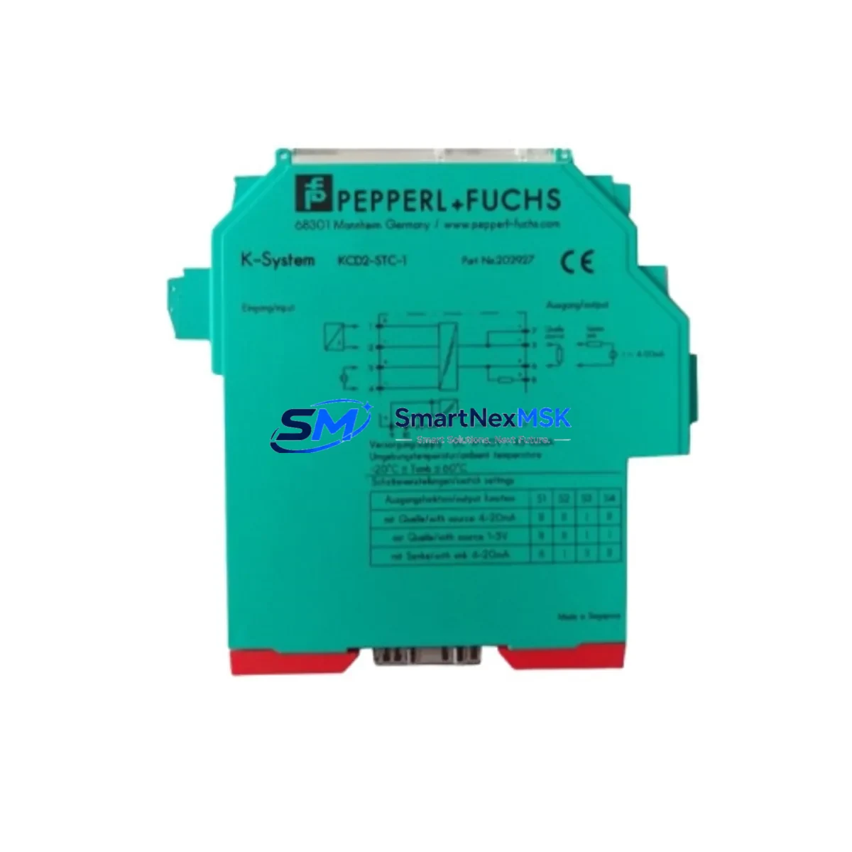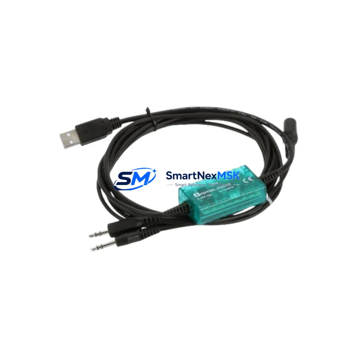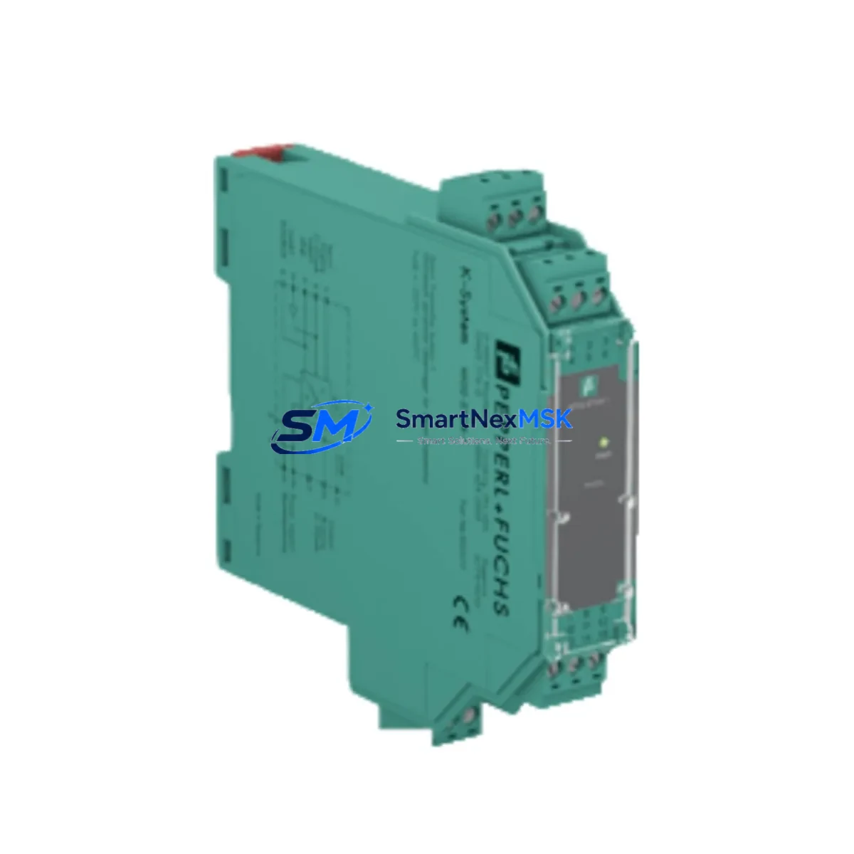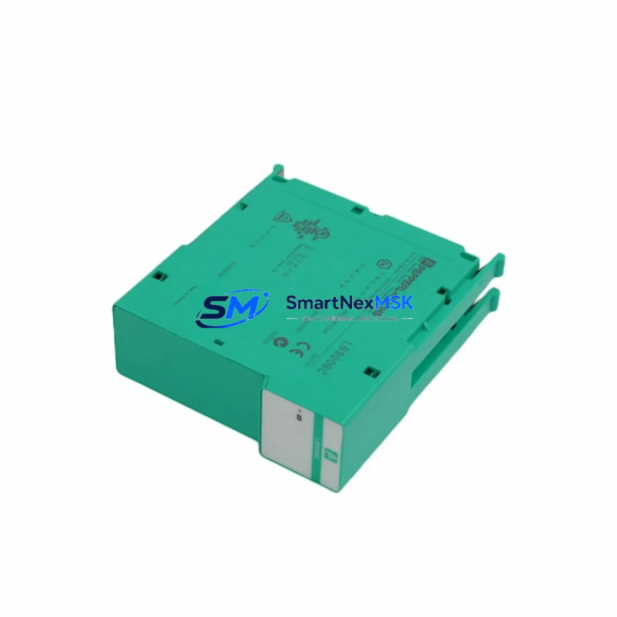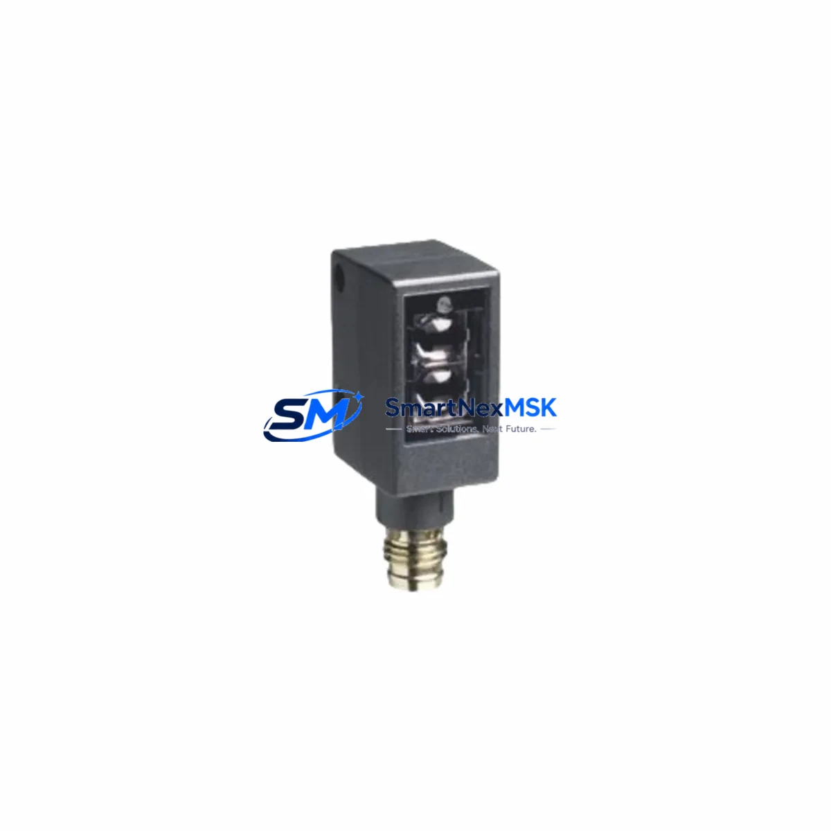
Pepperl+Fuchs ML4.2-8-H-20-IR/40B/95/110 Maintenance-Ready Spare for ML4.2 Automation
The Pepperl+Fuchs ML4.2-8-H-20-IR/40B/95/110 is a background suppression (BGS) photoelectric sensor from the ML4.2 series, engineered for precision object detection in demanding industrial automation environments. As a maintenance-ready spare, this unit is stocked and tested to support rapid field replacement, minimizing unplanned downtime in production lines, conveyor systems, packaging machinery, and automated assembly cells. Whether you are executing a planned shutdown, responding to a sensor fault, or building a preventive maintenance inventory, the ML4.2-8-H-20-IR/40B/95/110 delivers the original Pepperl+Fuchs performance your system was designed around.
Sourced directly from authorized supply channels, each unit undergoes pre-shipment functional verification. A 12-month warranty is included, covering defects in materials and workmanship under normal operating conditions. Global logistics support ensures fast dispatch to maintenance teams across manufacturing, automotive, food and beverage, and logistics automation sectors.
Spare Maintenance Table
| Parameter | Specification |
|---|---|
| Part Number / SKU | ML4.2-8-H-20-IR/40B/95/110 |
| Brand | Pepperl+Fuchs |
| Series | ML4.2 |
| Detection Mode | Background Suppression (BGS) |
| Light Source | Infrared (IR) |
| Sensing Range | 20–200 mm (adjustable) |
| Supply Voltage | 10–30 V DC |
| Output Type | PNP / NPN, push-pull |
| Housing | Compact rectangular, M8 connector |
| Protection Rating | IP67 |
| Operating Temperature | -40 °C to +60 °C |
| Country of Origin | Germany |
| Compatibility | Direct replacement for ML4.2 series BGS variants; compatible with standard M8 4-pin wiring |
| Warranty | 12 Months |
| Pre-Shipment Test | Functional verification included |
Maintenance Planning for Continuous Operation
When replacing the ML4.2-8-H-20-IR/40B/95/110 in the field, maintenance engineers should treat the sensor swap as part of a broader inspection of the surrounding detection circuit and control cabinet. A single sensor fault often signals stress on adjacent components that share the same power rail or I/O channel.
Begin by verifying the 24 V DC supply rail feeding the sensor. A degraded or noisy power supply module — such as a SITOP PSU100S or equivalent DIN-rail power supply — can cause intermittent BGS sensor faults that mimic mechanical misalignment. Inspect the M8 sensor cable and connector for insulation damage, pin corrosion, or intermittent contact; a faulty sensor cable is a common root cause of false fault codes before the sensor itself fails.
Check the corresponding digital input channel on the PLC I/O module. For Siemens S7-300 or S7-1200 systems, inspect the SM 321 or SM 1221 digital input card for channel-level faults or blown input protection. If the ML4.2 sensor feeds a safety-rated zone, verify the associated safety relay module — such as a Pilz PNOZ or Siemens 3SK1 — for correct response time and contact integrity.
For installations where the ML4.2-8-H-20-IR/40B/95/110 is wired through a terminal block assembly, inspect the Weidmüller or Phoenix Contact terminal strips for loose screws, oxidized contacts, or overheating marks. A signal isolator or Pepperl+Fuchs KFD2-series barrier in the circuit should also be checked for output drift if the sensor is used in a Zone 2 or intrinsically safe application.
If the system uses a Pepperl+Fuchs VariKont or ML100 series sensor in adjacent detection positions, cross-check their alignment and sensitivity settings during the same maintenance window to avoid repeat callouts. For conveyor indexing applications, also inspect the encoder or proximity switch on the same axis — a Pepperl+Fuchs NBB or NJ series inductive proximity sensor sharing the same I/O group may exhibit similar wear patterns.
Maintaining a minimum of two ML4.2-8-H-20-IR/40B/95/110 units in your on-site spare parts cabinet is recommended for high-cycle production environments. Pair this with a documented sensor map showing mounting positions, teach settings, and cable routing to accelerate future replacements and reduce mean time to repair (MTTR).
Site Replacement Workflow
Step 1 — Isolation: De-energize the machine zone and lock out the 24 V DC supply to the sensor circuit. Confirm zero voltage at the M8 connector before disconnecting.
Step 2 — Documentation: Photograph the existing sensor mounting angle, teach potentiometer position, and cable routing before removal. This preserves the original detection geometry for the replacement unit.
Step 3 — Mechanical Swap: Remove the faulty ML4.2-8-H-20-IR/40B/95/110 from its bracket. The ML4.2 series uses a standard compact housing with M3 or M4 mounting holes — the replacement unit is a direct mechanical fit with no bracket modification required.
Step 4 — Wiring: Connect the replacement sensor using the original M8 cable. Verify pin assignment: Pin 1 = +V DC, Pin 3 = 0 V, Pin 4 = Output. For push-pull output variants, confirm PLC input card compatibility before energizing.
Step 5 — Teach and Verify: Re-energize the circuit and perform a BGS teach cycle using the sensor’s teach button or IO-Link parameterization if applicable. Confirm stable output signal with the target object at the nominal detection distance. Check PLC diagnostic screen for clean input state.
Step 6 — System Restart: Clear any latched fault codes in the PLC or HMI. Resume production and monitor the first 10–15 cycles to confirm consistent detection performance before returning the machine to full speed.
This workflow applies equally to legacy ML4.2 installations and newer systems where the ML4.2-8-H-20-IR/40B/95/110 has been retrofitted as a drop-in replacement for discontinued sensor models. The standardized housing and wiring interface ensure backward compatibility without control program changes.
Spare Parts Support FAQ
Q1: Is the ML4.2-8-H-20-IR/40B/95/110 a genuine Pepperl+Fuchs original part?
Yes. All units supplied are sourced from authorized distribution channels and carry the original Pepperl+Fuchs part marking. Each unit is functionally tested prior to shipment to confirm output switching, supply voltage tolerance, and BGS detection performance.
Q2: What is the warranty coverage and how is it claimed?
A 12-month warranty is provided from the date of shipment, covering manufacturing defects under normal operating conditions. To initiate a warranty claim, contact [email protected] with your order reference, a description of the fault, and photographic evidence of the installation. Replacement or refund is processed within 5 business days of fault confirmation.
Q3: Can this sensor replace older or discontinued ML4.2 variants?
The ML4.2-8-H-20-IR/40B/95/110 is compatible with standard ML4.2 series mounting brackets and M8 wiring harnesses. It can serve as a functional replacement for earlier BGS variants in the same series provided the supply voltage, output type, and sensing range requirements match. Compatibility verification against your existing wiring diagram is recommended before installation.
Q4: What is the typical lead time and how are units packaged for shipment?
In-stock units are dispatched within 1–3 business days. Each sensor is individually packaged in anti-static protective packaging with a pre-shipment test report included. Express courier options are available for emergency maintenance situations. Long-term supply agreements and blanket orders are supported for customers requiring ongoing spare parts inventory management.
© 2026 SMARTNEXMSK. All rights reserved.
Original Source: https://smartnexmsk.com
Contact: [email protected] | +86 18259474341