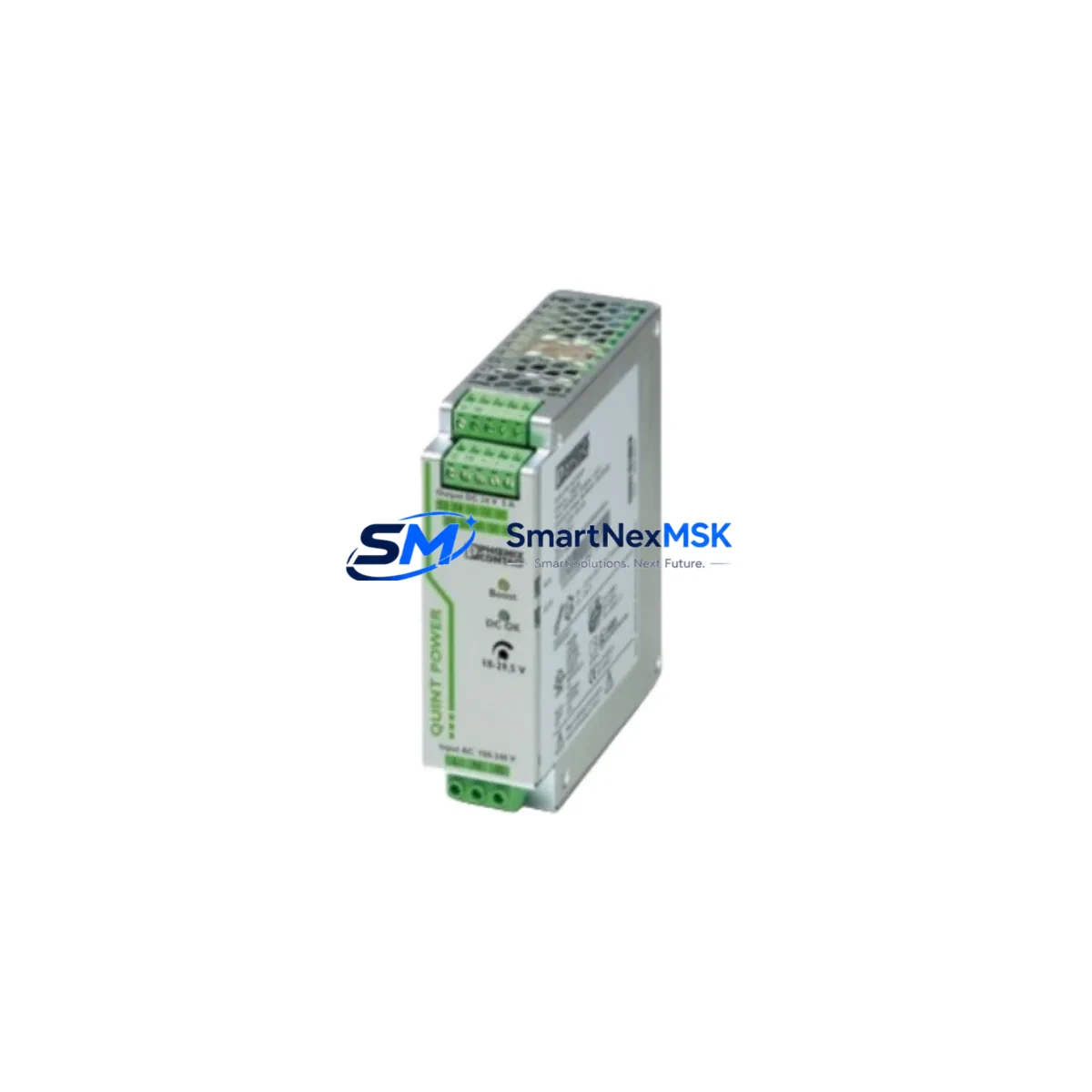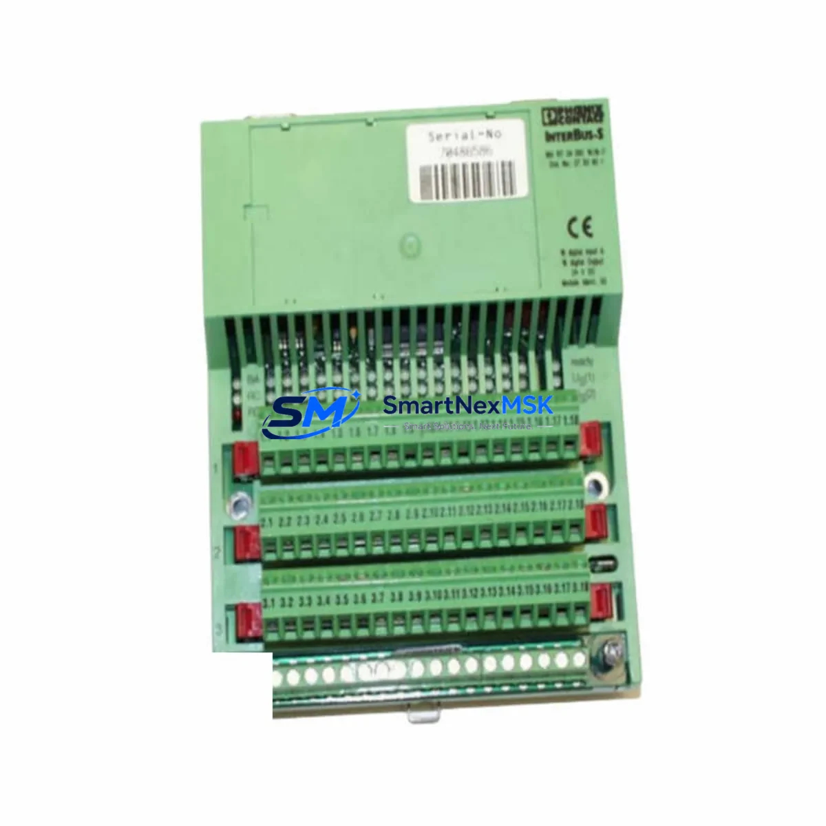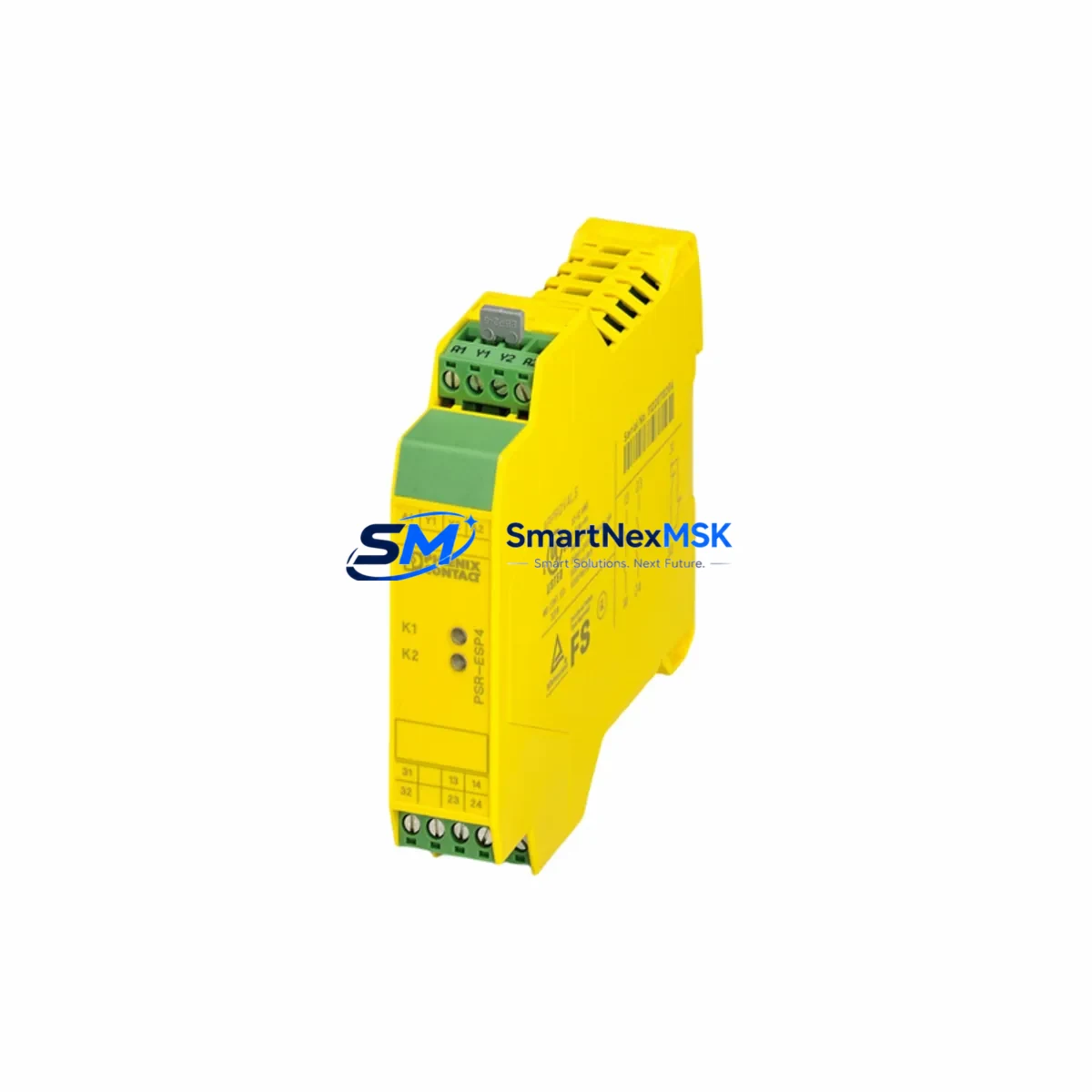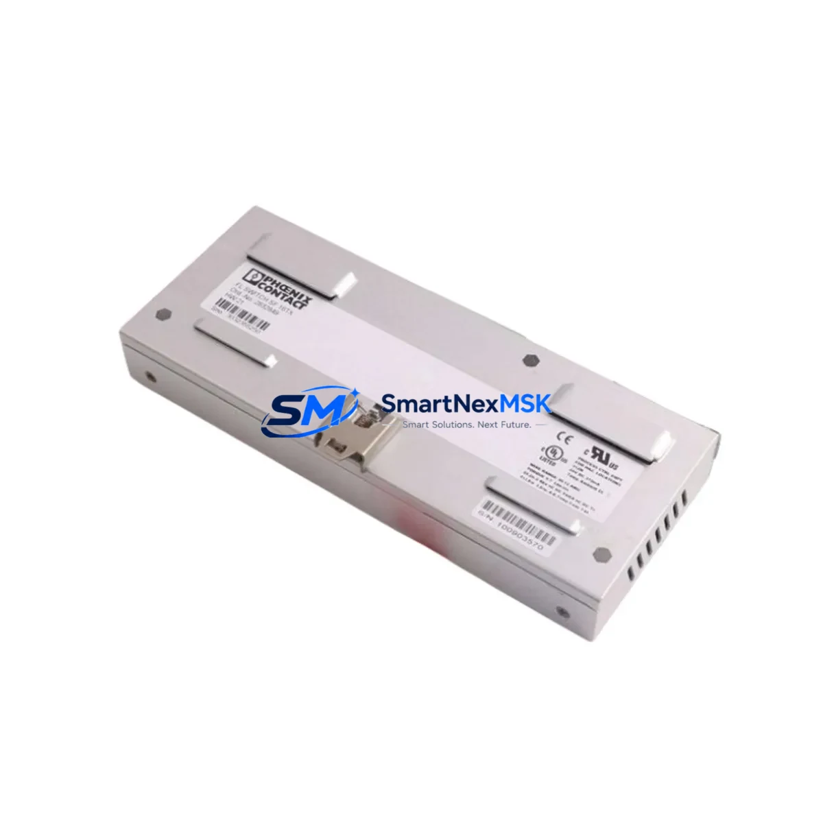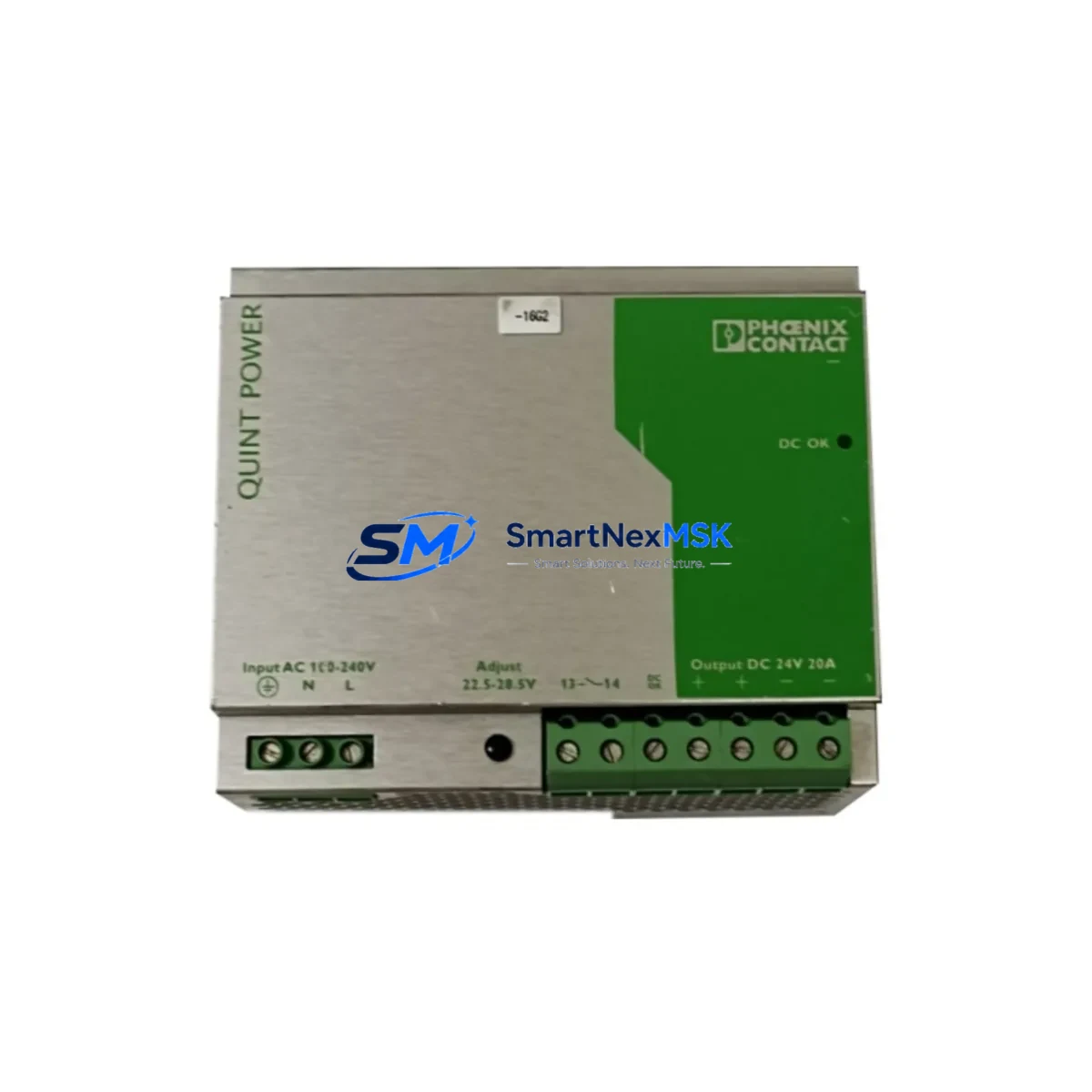
Phoenix Contact 1053835-100 Spare for TRIO POWER Automation
The Phoenix Contact 1053835-100 is a primary-switched DIN rail power supply from the TRIO POWER series, delivering a regulated 24 VDC output for industrial control panels, PLC racks, and distributed automation systems. As a maintenance-ready original spare, this unit is stocked and tested to support rapid replacement during planned shutdowns and unplanned fault events. Downtime in industrial environments carries direct operational cost — having a verified, compatible spare on the shelf is the most effective insurance against extended outages caused by power supply failure.
Maintenance engineers working on Phoenix Contact TRIO POWER installations will recognize the 1053835-100 as a direct fit for 24 VDC bus segments powering field I/O, relay output modules, and communication gateways. Its compact DIN rail form factor and wide-range AC input make it a reliable backbone component in both legacy and current-generation control cabinets. Each unit shipped from our inventory undergoes functional verification and is covered by a 12-month warranty from the date of dispatch.
Spare Maintenance Table
| Parameter | Specification |
|---|---|
| Part Number / SKU | 1053835-100 |
| Brand | Phoenix Contact |
| Series | TRIO POWER |
| Output Voltage | 24 VDC (regulated) |
| Input Voltage Range | 85–264 VAC / 90–350 VDC (wide range) |
| Mounting | DIN rail (EN 60715 TH35) |
| Protection Class | IP20 |
| Origin | Germany (DE) |
| Product Type | Industrial Power Supply |
| Compatibility | Phoenix Contact TRIO POWER series; direct replacement for 1053835-100 installations |
| Application Environment | Industrial control panels, PLC racks, DCS marshalling cabinets, MCC panels |
| Maintenance Recommendation | Inspect output terminals, check load current, verify LED status indicators at each scheduled PM cycle |
| Warranty | 12 months from date of shipment |
| Condition | Original, new-in-box; functionally tested before dispatch |
Maintenance Planning for Continuous Operation
When a TRIO POWER 1053835-100 unit is flagged for replacement — whether during a scheduled outage or an emergency fault response — experienced maintenance engineers know that the power supply is rarely the only component that warrants attention. A systematic cabinet inspection at the time of replacement significantly reduces the risk of a repeat callout.
Begin by verifying the incoming AC supply through the upstream circuit breaker or fuse, such as a Phoenix Contact PTFIX or CLIPLINE terminal block assembly feeding the PSU input. Check for signs of thermal stress or loose terminations on the 24 VDC bus bar and downstream PTFIX distribution blocks. If the cabinet includes a Phoenix Contact UNO POWER or QUINT POWER unit on a parallel bus segment, inspect its output voltage and ripple under load — a failing secondary PSU can mask the root cause of the primary fault.
On the load side, inspect the Phoenix Contact IB IL 24 DO 16 or comparable Inline I/O modules for overcurrent events that may have contributed to the PSU trip. Review the relay output modules — such as the PLC-RSC series — for contact wear or coil voltage anomalies, as inductive load switching is a common source of bus voltage dips. If the system uses a Phoenix Contact FL SWITCH managed Ethernet switch for PROFINET or EtherNet/IP communication, confirm that its 24 VDC input is within tolerance after the PSU swap, since communication faults often surface immediately after a power event.
For systems with Phoenix Contact MACX MCR signal conditioners or isolation amplifiers, verify that 4–20 mA loop integrity is maintained post-replacement — these devices are sensitive to supply voltage transients during power cycling. Similarly, check any MINI MCR-SL surge protection devices on analog and digital signal lines; a power fault event can degrade SPD clamping elements without triggering visible failure. Finally, confirm that the Phoenix Contact ILC 150 ETH or comparable ILC/RFC controller has completed a clean restart and that all I/O modules have re-initialized correctly before returning the system to automatic mode.
Stocking a TRIO POWER 1053835-100 alongside a small buffer of complementary components — terminal blocks, fuse holders, relay bases, and a spare communication module — transforms a reactive maintenance event into a controlled, time-bounded recovery procedure.
Site Replacement Workflow
Step 1 — Isolation: De-energize the cabinet section feeding the 1053835-100. Lock out / tag out per site procedure. Confirm zero voltage at PSU input terminals with a calibrated meter.
Step 2 — Documentation: Photograph terminal wiring and note the output load current from the existing unit’s LED or display before removal. Record the firmware or hardware revision label if visible.
Step 3 — Removal: Disconnect AC input wiring (L, N, PE) and 24 VDC output terminals. Release the DIN rail locking tab and slide the unit clear. Inspect the rail and adjacent components for heat damage or corrosion.
Step 4 — Installation: Clip the replacement 1053835-100 onto the DIN rail. Reconnect terminals in reverse order — PE first, then L and N, then 24 VDC output. Torque to Phoenix Contact specification (typically 0.5–0.6 Nm for TRIO POWER screw terminals).
Step 5 — Commissioning: Re-energize and verify output voltage at the PSU terminals (24.0–24.5 VDC nominal). Confirm green POWER OK LED. Check downstream I/O module status LEDs and controller diagnostic screen before releasing to production.
Step 6 — Documentation close-out: Update the maintenance log with part number, serial number, installation date, and technician ID. Flag the replaced unit for failure analysis if root cause has not been confirmed.
This workflow is compatible with direct replacement of earlier TRIO POWER variants and supports system continuity without firmware changes or parameter re-entry, minimizing total downtime to the physical swap and commissioning check.
Spare Parts Support FAQ
Q1: Is the 1053835-100 a direct drop-in replacement for older TRIO POWER units in the same series?
Yes. The 1053835-100 maintains the same DIN rail footprint, terminal layout, and 24 VDC output specification as predecessor TRIO POWER variants. No wiring modifications or parameter changes are required for a like-for-like swap in existing installations.
Q2: How is each unit tested before shipment?
Every 1053835-100 in our inventory is functionally verified under load prior to dispatch. Output voltage, ripple, and protection circuit response are confirmed. Units are packed in anti-static, shock-resistant packaging with a test record included in the shipment documentation.
Q3: What does the 12-month warranty cover?
The warranty covers manufacturing defects and functional failure under normal operating conditions for 12 months from the date of shipment. It does not cover damage resulting from incorrect installation, overvoltage events, or operation outside the rated input/output envelope. Warranty claims are processed with return authorization and a replacement unit dispatched within the agreed lead time.
Q4: Can you support long-term or blanket orders for TRIO POWER spares?
Yes. We support scheduled release orders, consignment stock arrangements, and multi-SKU spare parts kits for maintenance programs. Contact our team to discuss volume pricing, lead time commitments, and consolidated shipment options for TRIO POWER and related Phoenix Contact components.
© 2026 SMARTNEXMSK. All rights reserved.
Original Source: https://smartnexmsk.com
Contact: [email protected] | +86 18259474341