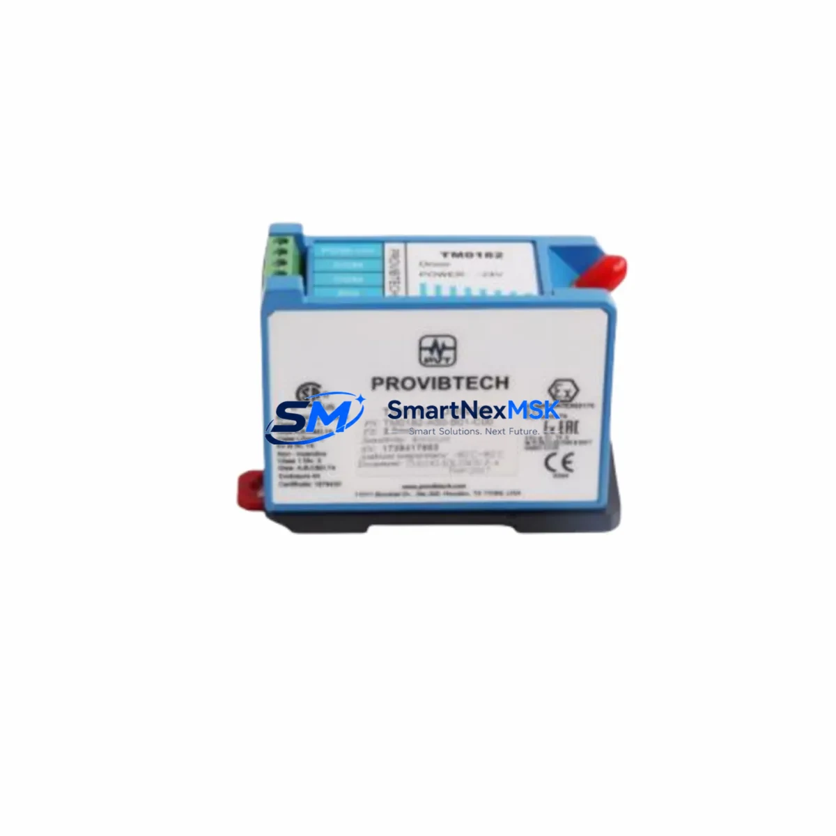
PROVIBTECH TM0182-A50-B01-C00 Maintenance-Ready Spare for TM Series Automation
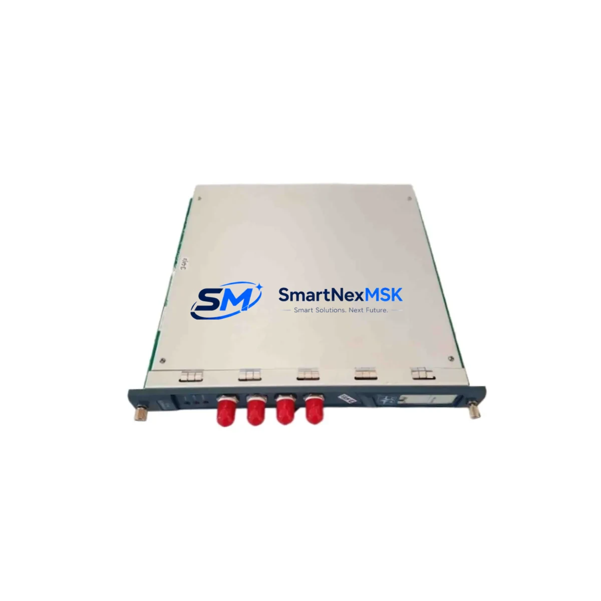
The PROVIBTECH TM0182-A50-B01-C00 is a dual-channel vibration monitoring module designed for continuous machinery protection in industrial automation environments. As a maintenance-ready spare, it is sourced as an original unit, fully tested prior to shipment, and backed by a 12-month warranty — making it a reliable choice for maintenance engineers managing rotating equipment protection systems, turbine monitoring panels, and compressor control cabinets.
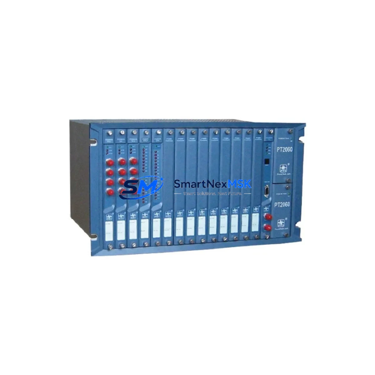
Unplanned downtime caused by a failed vibration monitoring channel can cascade rapidly across a protection system. Keeping a verified spare of the TM0182-A50-B01-C00 on the shelf eliminates the lead-time risk associated with OEM procurement and ensures that your TM Series rack can be restored to full operational status within a single maintenance window. This module is compatible with the PROVIBTECH TM Series modular rack architecture and is suitable for direct replacement in existing installations without requiring firmware reconfiguration in most standard deployments.
For maintenance planners and procurement engineers, this unit is an essential line item in any rotating equipment spare parts register — particularly for facilities operating gas turbines, steam turbines, centrifugal compressors, or large induction motors where continuous vibration surveillance is a regulatory or insurance requirement.
Spare Maintenance Table
| Parameter | Specification |
|---|---|
| Part Number | TM0182-A50-B01-C00 |
| Brand | PROVIBTECH |
| Series | TM Series |
| Module Type | Dual-Channel Vibration Monitoring Module |
| Input Channels | 2 (Dual-channel, independent signal processing) |
| Signal Input | Eddy current / velocity / acceleration sensor compatible |
| Output | 4–20 mA analog output per channel; relay alarm output |
| Power Supply | 24 VDC (rack-supplied via TM Series backplane) |
| Operating Temperature | 0°C to +60°C |
| Mounting | TM Series modular rack, DIN-compatible backplane |
| Protection Rating | IP20 (panel-mount installation) |
| Origin | China (OEM-sourced, original unit) |
| Compatibility | PROVIBTECH TM Series racks; replaces legacy TM0182 variants |
| Warranty | 12 Months from date of shipment |
| Pre-shipment Test | Function-tested; includes inspection report on request |
| Maintenance Recommendation | Inspect connector pins and backplane contacts at each planned shutdown; replace if channel drift exceeds ±2% of full scale |
Maintenance Planning for Continuous Operation
When replacing the TM0182-A50-B01-C00 in a live protection system, a disciplined maintenance workflow requires more than a module swap. Maintenance engineers should treat this replacement as an opportunity to audit the surrounding electrical environment and confirm that adjacent components are not contributing to the fault condition or masking a deeper system issue.
Begin with the TM Series power supply module (typically a TM0100 or equivalent rack power unit): verify output voltage stability under load, as a sagging 24 VDC rail is a common root cause of spurious vibration alarms and premature module failure. Next, inspect the TM Series backplane or rack chassis for oxidized connector contacts, which can introduce intermittent signal loss on either channel of the monitoring module.
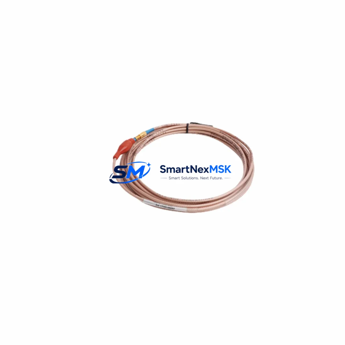
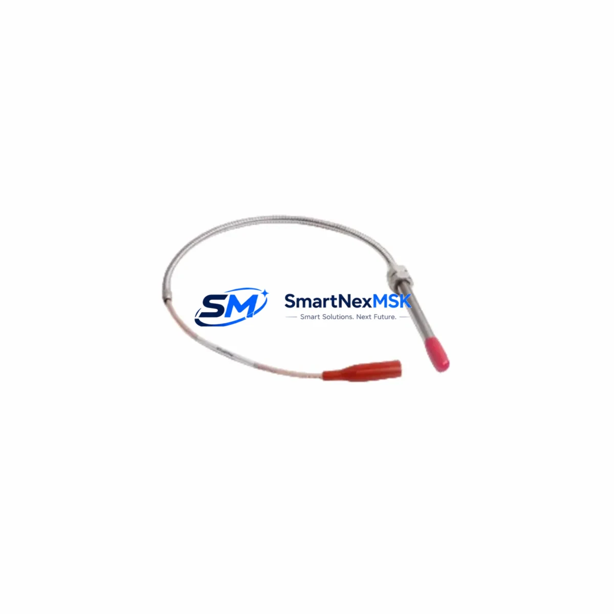
On the sensor side, confirm that the eddy current proximity probes and their associated extension cables and driver/oscillator units are within calibration. A failed or drifting proximity probe driver will produce erroneous gap voltage readings that the TM0182-A50-B01-C00 cannot distinguish from genuine shaft vibration — leading to nuisance trips or, worse, missed alarm conditions. If the installation uses velocity transducers or accelerometers, check connector integrity and cable shielding continuity at both the sensor junction box and the rack terminal strip.
For systems with relay-based alarm outputs, inspect the interposing relay modules connected to the TM0182 alarm contacts. Relay coil resistance and contact resistance should be verified; a high-resistance contact can prevent alarm activation during a genuine trip event. Similarly, review the terminal blocks and field wiring at the rack marshalling panel — loose terminations are a leading cause of intermittent channel faults in vibration monitoring systems.
If the TM Series rack communicates with a DCS or safety PLC via 4–20 mA analog inputs or Modbus RTU, verify that the receiving I/O card is reading the correct engineering-unit values after module replacement. In some installations, a signal isolator or barrier is installed between the TM rack output and the DCS analog input card; confirm that the isolator is functioning correctly and has not introduced a calibration offset. Finally, if the facility uses an HMI or SCADA system to display vibration trends, confirm that the tag mapping and alarm setpoints are correctly restored after the module is returned to service.
Site Replacement Workflow
Step 1 — Isolation and permit: Obtain a valid work permit and isolate the affected monitoring channel per your site’s machinery protection bypass procedure. Do not remove the module under live rack power unless your site procedure explicitly permits hot-swap operations for this rack type.
Step 2 — Document baseline: Record the current vibration readings, alarm setpoints, and relay configuration from the existing module or from the DCS historian before removal. This baseline is essential for post-replacement verification.
Step 3 — Module removal: Disconnect field wiring at the terminal strip, release the module locking mechanism, and extract the TM0182-A50-B01-C00 from the rack slot. Inspect the backplane connector for bent pins or contamination before inserting the replacement unit.
Step 4 — Replacement installation: Insert the new TM0182-A50-B01-C00, reconnect field wiring per the original termination schedule, and restore rack power. Allow the module a 2–5 minute warm-up period before comparing output readings against the documented baseline.
Step 5 — Functional verification: Confirm that both channels are reading within expected range, that relay outputs respond correctly to a simulated trip condition, and that the DCS or HMI is displaying correct values. Update the maintenance log and spare parts register accordingly.
This workflow minimizes downtime exposure and ensures that the replacement module is confirmed operational before the machinery protection bypass is lifted — a critical step for facilities subject to API 670 or equivalent machinery protection standards.
Spare Parts Support FAQ
Q1: Is the TM0182-A50-B01-C00 an original PROVIBTECH unit or a compatible replacement?
All units supplied are original PROVIBTECH manufacture, sourced through established industrial distribution channels. Each unit undergoes functional testing prior to shipment. A test report is available on request. We do not supply counterfeit, refurbished-as-new, or third-party compatible substitutes under this part number.
Q2: What is the warranty coverage and what does it include?
Each TM0182-A50-B01-C00 is covered by a 12-month warranty from the date of shipment. The warranty covers manufacturing defects and functional failure under normal operating conditions. It does not cover damage resulting from incorrect installation, overvoltage, or physical impact. Warranty claims are processed with return shipping support and priority replacement dispatch.
Q3: Can this module directly replace older TM0182 variants without rack reconfiguration?
In most standard TM Series rack installations, the TM0182-A50-B01-C00 is a direct drop-in replacement for earlier TM0182 suffix variants. However, we recommend confirming the rack firmware version and any site-specific configuration parameters with your maintenance documentation before installation, particularly in safety-instrumented system (SIS) applications where change management procedures apply.
Q4: What is the typical lead time and do you maintain stock for emergency orders?
We maintain buffer stock of high-demand PROVIBTECH TM Series modules to support emergency replacement scenarios. Standard orders are dispatched within 1–3 business days. For urgent shutdown recovery situations, contact our sales team directly to confirm same-day or next-day dispatch availability. Long-term blanket order arrangements are available for facilities with recurring spare parts requirements.
© 2026 SMARTNEXMSK. All rights reserved.
Original Source: https://smartnexmsk.com
Contact: [email protected] | +86 18259474341