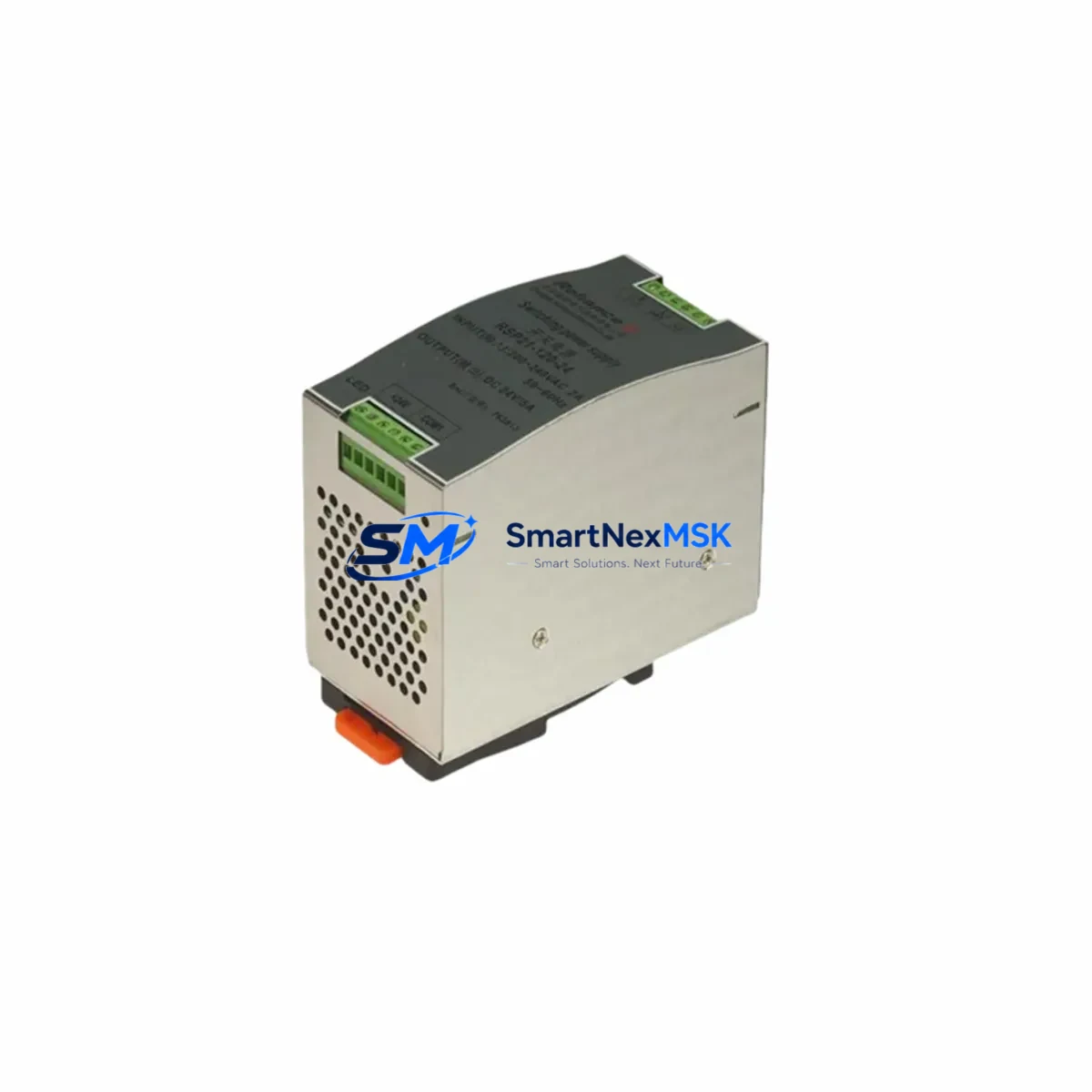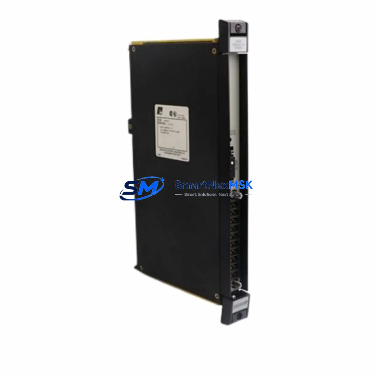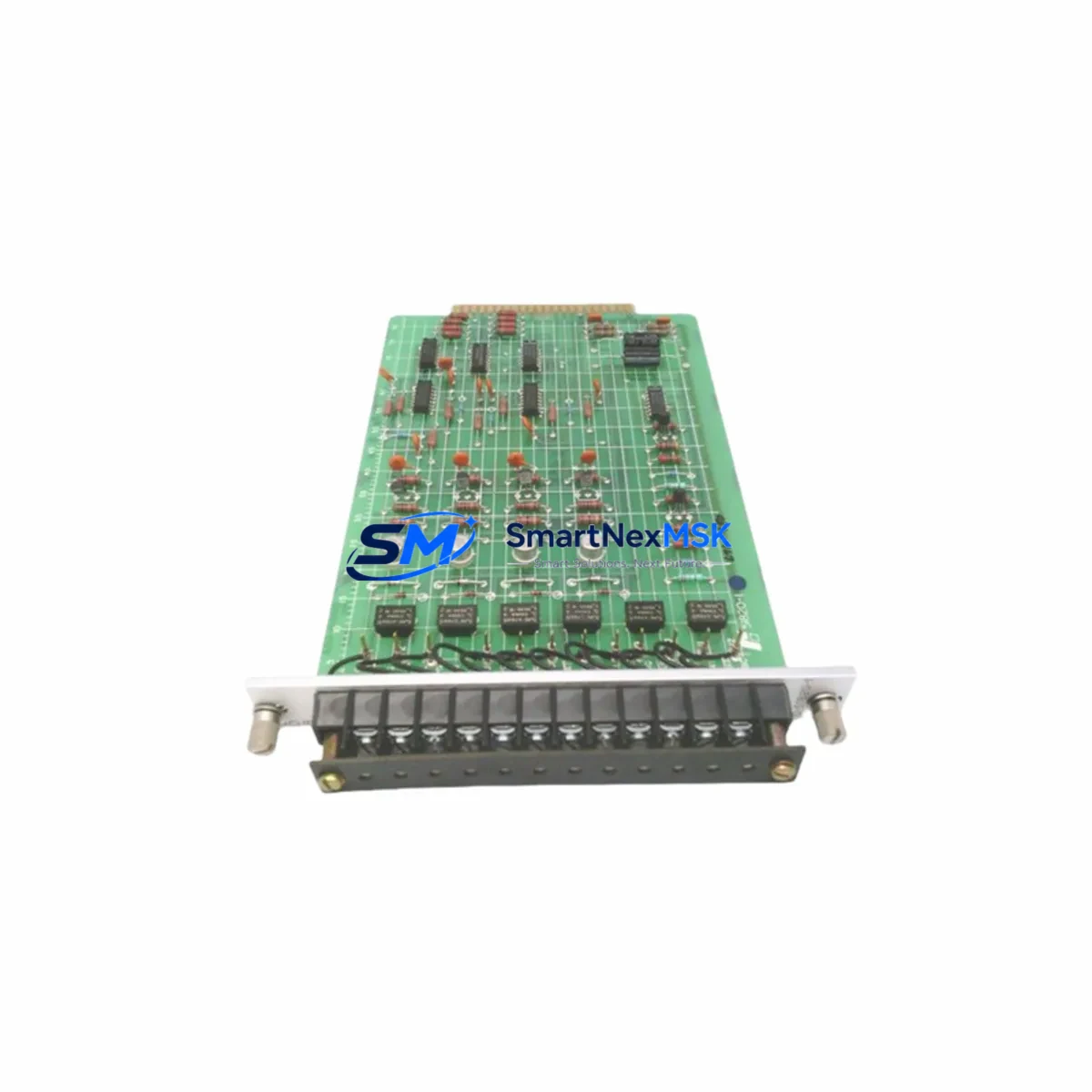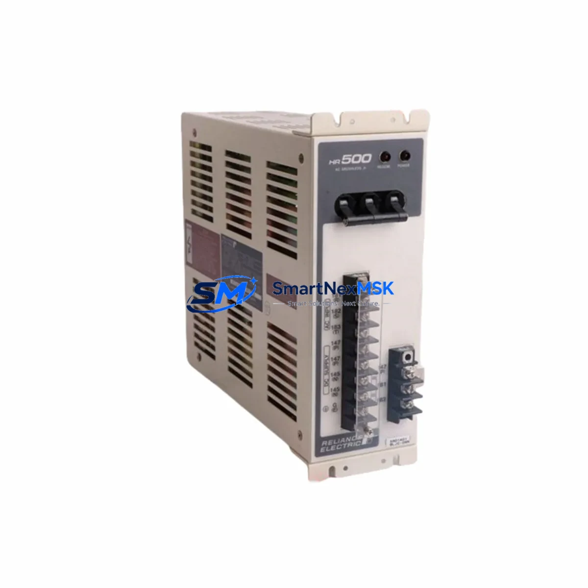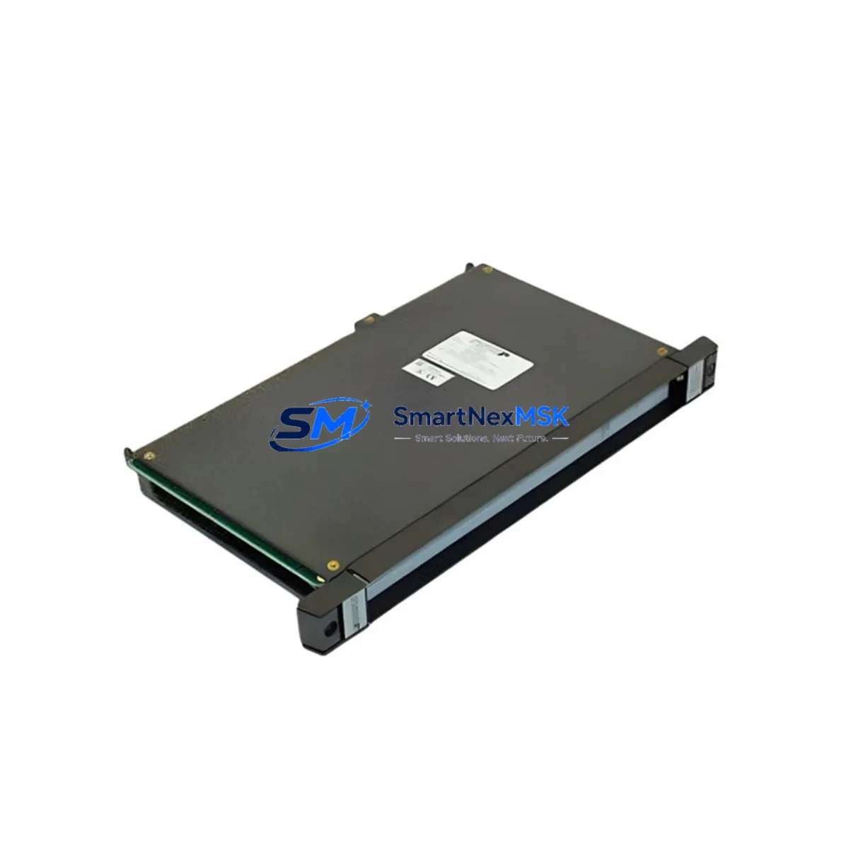
RELIANCE 0-57405-D Retrofit-Ready Analog I/O Module for Drive Series Control Systems
The RELIANCE Electric 0-57405-D (also referenced as 57405-D) is a proven Analog I/O Module engineered for seamless integration into RELIANCE Drive Series control architectures. As legacy automation systems reach end-of-life and OEM support is discontinued, the 0-57405-D remains a critical retrofit component for engineers tasked with sustaining production continuity, upgrading aging control cabinets, and migrating I/O infrastructure without full system replacement.
Whether you are replacing a failed module in an active production line, sourcing a tested spare for a planned maintenance window, or executing a phased migration from an obsolete drive platform to a modern control topology, the 0-57405-D delivers the analog signal conditioning and I/O interface performance required by Drive Series backplane architectures. All units are fully tested prior to shipment, backed by a 12-month warranty, and available for fast global dispatch from verified inventory.
Upgrade Compatibility Table
| Parameter | Details |
|---|---|
| SKU / Part Number | 0-57405-D / 57405-D |
| Brand | RELIANCE Electric |
| Series Compatibility | Drive Series (RELIANCE Electric) |
| Module Type | Analog I/O Module |
| Installation | Backplane-mounted; verify slot addressing and rack configuration before installation |
| Interface / Communication | Drive Series backplane bus; confirm signal wiring and terminal block pinout against original drawings |
| Replacement Suitability | Direct retrofit replacement for failed or discontinued 0-57405-D units in Drive Series panels |
| Commissioning Notes | Verify module address, analog channel scaling, and program tag mapping after swap |
| Pre-Shipment Testing | Fully tested and verified before dispatch |
| Warranty | 12-Month Warranty included |
Retrofit Planning for Existing Automation Systems
Successful integration of the 0-57405-D into an existing Drive Series control system requires careful pre-installation planning. Before removing the failed module, engineers should document the existing terminal block wiring layout, confirm the analog channel assignments in the current PLC program, and photograph the physical installation for reference during reassembly.
In Drive Series architectures, the analog I/O module typically shares a rack or chassis with the main drive controller, power supply module, and digital I/O cards. When planning the retrofit, confirm that the rack’s backplane bus is intact and that the slot address assigned to the 0-57405-D matches the address configured in the control program. If the system uses a RELIANCE AutoMax or GP2000 series controller as the host processor, verify that the I/O map and module configuration table reflect the correct slot assignment before powering up the replacement module.
For systems that include a RELIANCE FlexPak 3000 or SP500 drive communicating over a serial or proprietary drive network, the analog reference signals routed through the 0-57405-D must be re-verified after module replacement to ensure speed reference and feedback scaling remain within specification. In multi-drive panels where a RELIANCE 0-57404-D digital I/O module or a 0-57406-D communication interface module is installed alongside the analog module, confirm that the inter-module signal routing and power distribution from the rack power supply are unaffected by the swap.
Terminal block compatibility is a common concern during retrofit. The 0-57405-D uses a standard Drive Series terminal interface; however, if the original wiring harness shows signs of insulation degradation or if the field wiring gauge does not match the terminal torque specification, re-termination is recommended before commissioning. Where a RELIANCE 0-51868 programming cable or equivalent interface is used to connect a programming workstation to the drive controller, ensure the communication link remains stable throughout the module swap process to allow live program monitoring.
In facilities where a RELIANCE GV3000 or GV3000/SE AC drive is part of the same control cabinet, the analog reference wiring from the 0-57405-D to the drive’s analog input terminals should be verified for shielding continuity and grounding integrity, particularly in high-noise industrial environments. If the system includes an HMI panel — such as a RELIANCE-compatible operator interface or a third-party panel view — confirm that the analog process variable displays and setpoint entry screens reflect the correct engineering unit scaling after the module is replaced and the program is restarted.
Downtime Control During System Migration
Minimizing unplanned downtime is the primary operational concern when replacing an analog I/O module in a live production environment. The recommended approach is to perform the 0-57405-D swap during a scheduled maintenance window, with the drive system placed in a controlled stop state and all analog outputs verified at zero before the module is removed from the backplane.
Before powering down, use the programming workstation to capture a full backup of the current PLC or drive controller program, including all analog scaling parameters, PID loop tuning values, and I/O force tables. This backup ensures that if the replacement module requires any address or configuration adjustment, the original logic can be restored without relying on paper documentation alone.
During the physical swap, avoid disturbing adjacent modules in the rack. The Drive Series backplane is sensitive to mechanical stress on connector pins; use the module extraction handle if present, and inspect the backplane connector on the replacement 0-57405-D for any bent or contaminated pins before insertion. After seating the module, restore power incrementally — energize the rack power supply first, confirm the module status indicator, then re-enable the drive controller and verify analog channel outputs against known reference values before returning the system to automatic operation.
For critical processes where even a brief interruption is unacceptable, consider pre-staging the replacement 0-57405-D in a bench test environment using a spare rack and power supply to verify module functionality before the scheduled swap. This approach, combined with a pre-written commissioning checklist covering terminal verification, address confirmation, program tag mapping, HMI display validation, and communication link testing, consistently reduces field commissioning time and protects original program logic integrity.
Retrofit Support FAQ
Q: Is the 0-57405-D a direct drop-in replacement for the original RELIANCE Drive Series analog I/O module?
A: Yes. The 0-57405-D is designed as a direct retrofit replacement for the original Drive Series analog I/O module of the same part number. Physical dimensions, backplane connector pinout, and analog channel configuration are identical to the original specification. Verify slot address and terminal wiring before powering up.
Q: What commissioning steps are required after installing the replacement module?
A: After physical installation, confirm the module slot address in the drive controller configuration, verify analog channel scaling and engineering unit assignments in the PLC program, check terminal block wiring continuity, and validate analog output values against process reference points. If an HMI is connected, confirm that all analog displays and setpoint screens reflect correct values before returning to automatic mode.
Q: How do I verify wiring compatibility between the 0-57405-D and my existing field wiring?
A: Reference the original Drive Series wiring diagram for the 0-57405-D terminal block pinout. Confirm field wire gauge, shielding, and grounding against the module’s terminal specification. Re-terminate any wiring that shows insulation damage or does not meet the torque specification. In high-noise environments, verify analog signal shielding is grounded at a single point to prevent ground loops.
Q: What does the 12-month warranty cover, and how are units tested before shipment?
A: Every 0-57405-D unit is functionally tested prior to shipment to verify analog I/O channel performance, backplane interface integrity, and module communication. The 12-month warranty covers manufacturing defects and functional failures under normal operating conditions. Units that fail within the warranty period are replaced or repaired at no additional cost. Contact our technical team for warranty claims or pre-shipment test documentation requests.
© 2026 SMARTNEXMSK. All rights reserved.
Original Source: https://smartnexmsk.com
Contact: [email protected] | +86 18259474341