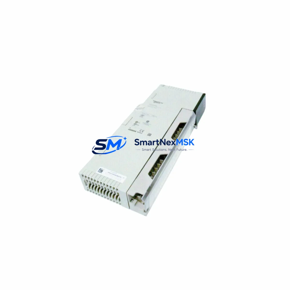
Schneider 140-DAI-540-00 Retrofit-Ready Discrete Input Module: Compatible Upgrade for Modicon Quantum Control Systems
The Schneider Electric 140-DAI-540-00 is a 32-channel, 24VDC discrete input module engineered for the Modicon Quantum automation platform. As legacy Quantum systems approach end-of-life and spare parts become increasingly scarce, the 140-DAI-540-00 remains one of the most sought-after retrofit components for engineers tasked with sustaining or modernizing existing control architectures. Whether you are replacing a failed module in a running production line, upgrading a control cabinet to extend operational life, or migrating I/O capacity to support expanded process requirements, this module delivers the electrical and logical compatibility required for a smooth, low-risk transition.
Designed to seat directly into the Modicon Quantum backplane — including the 140-XBP-016-00 and 140-XBP-010-00 rack assemblies — the 140-DAI-540-00 requires no hardware modification to the existing chassis. The module occupies a standard single-slot position and draws power from the backplane bus supplied by the 140-CPS-111-00 or 140-CPS-124-00 power supply modules. Before installation, engineers should verify that the rack’s total power budget accommodates the additional current draw, particularly in densely populated cabinets where multiple I/O modules share a common supply rail.
Terminal wiring follows the standard Modicon Quantum discrete input convention. Field devices connect via the 140-XTS-002-00 terminal strip or equivalent screw-terminal block, with each of the 32 input channels mapped to a dedicated terminal pair. During retrofit planning, it is critical to document the original wiring schedule from the as-built drawings before disconnecting any field cables. Input signal polarity, common return routing, and surge suppression requirements should be confirmed against the field device specifications to avoid nuisance trips or input damage after commissioning.
Module addressing is configured through the Unity Pro or Concept programming environment. When replacing a failed 140-DAI-540-00 in an existing rack, the replacement module inherits the slot address automatically, provided the rack configuration in the PLC project file has not been altered. For new rack positions or expanded I/O configurations, the module address must be declared in the hardware configuration editor and the project must be downloaded to the 140-CPU-651-60 or equivalent Quantum CPU before the new inputs become active in the control logic. Engineers should perform a full I/O forcing test on all 32 channels prior to returning the system to automatic operation.
Program compatibility is a key concern during any Quantum retrofit. The 140-DAI-540-00 uses the same data structure and I/O mapping conventions as earlier Quantum discrete input modules, which means existing ladder logic, function block diagrams, and structured text routines referencing the original module’s %I addresses will continue to function without modification. However, if the retrofit is part of a broader migration from an older Modicon 984 or Compact TSX platform, the I/O variable mapping must be re-declared in the Unity Pro project to align with the Quantum addressing scheme.
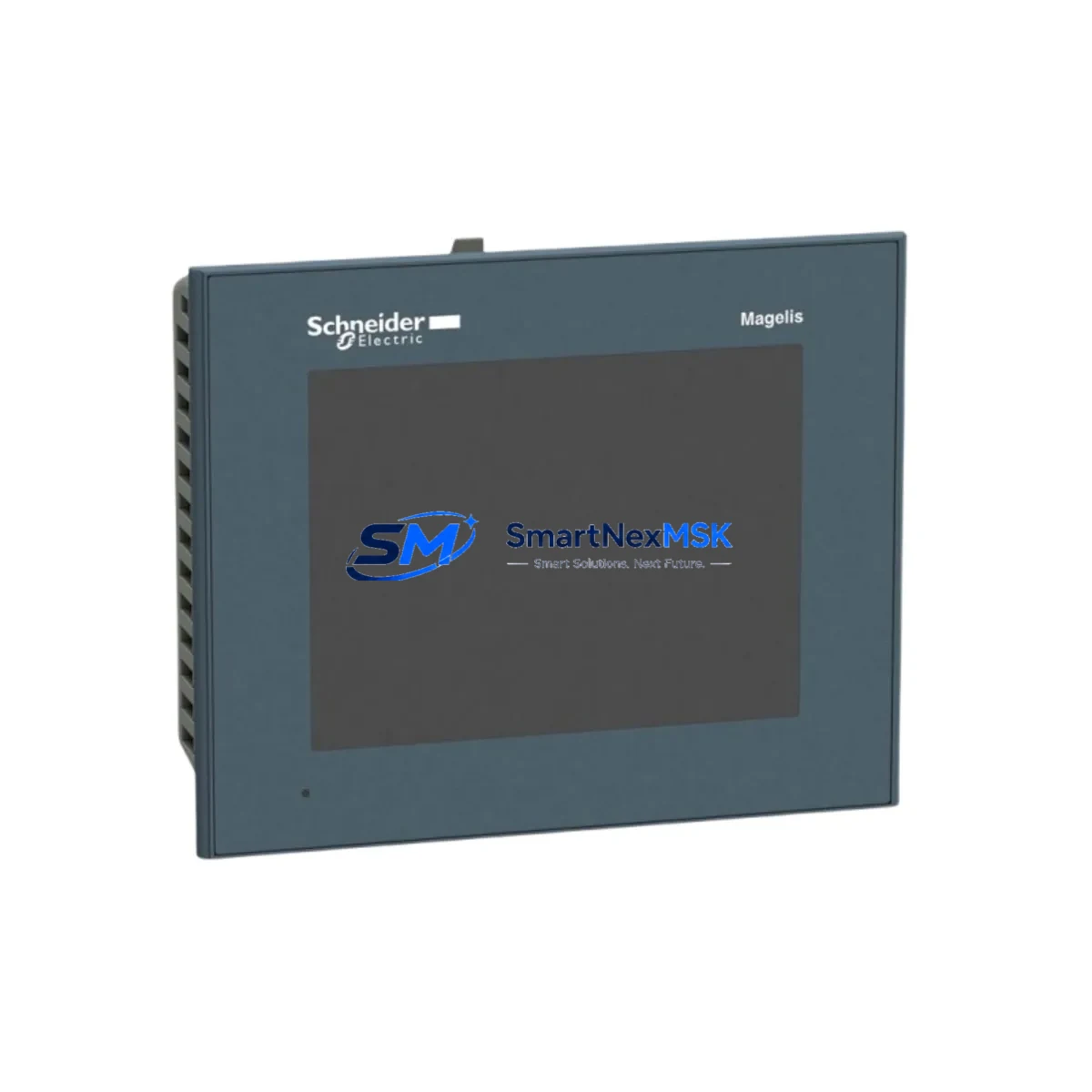
HMI screen updates are often overlooked during module-level retrofits. If the control system includes a Magelis XBTGT or XBTGK operator panel communicating via Modbus TCP or Uni-Telway, the HMI project should be reviewed to confirm that any discrete input status displays, alarm triggers, or interlock indicators referencing the replaced module’s addresses remain valid after the retrofit. A mismatch between the HMI variable table and the updated PLC configuration can result in silent failures that are difficult to diagnose during post-commissioning verification.
Communication link integrity must also be verified when the 140-DAI-540-00 is installed in a distributed I/O drop connected via the 140-NOM-211-00 Modbus Plus network module or the 140-NOE-771-01 Ethernet TCP/IP module. In remote drop configurations, the I/O scanner cycle time and the RIO head adapter — typically a 140-CRA-931-00 — must be checked to ensure the new module’s data is correctly polled and reflected in the master CPU’s I/O image table. Any change to the drop’s module population requires a corresponding update to the RIO configuration in the Unity Pro hardware editor.
Field commissioning for a 140-DAI-540-00 retrofit typically follows a structured sequence: power-down the affected rack section, seat the replacement module, restore rack power, verify the module’s RUN LED status, force each input channel from the programming terminal, confirm the corresponding %I bit state in the PLC data table, and release the system to normal operation. This sequence minimizes unplanned downtime and provides a documented verification record for maintenance logs and regulatory compliance requirements.
All units supplied by SMARTNEXMSK are sourced from verified industrial channels, functionally tested prior to shipment, and covered by a 12-month warranty against manufacturing defects and operational failure. Stock is maintained in Xiamen for prompt dispatch to domestic and international customers.
Upgrade Compatibility Table
| Parameter | 140-DAI-540-00 Specification | Retrofit / Upgrade Notes |
|---|---|---|
| Platform Compatibility | Modicon Quantum | Direct slot replacement; no chassis modification required |
| Input Channels | 32 channels, 24VDC | Identical channel count to predecessor modules; wiring schedule preserved |
| Backplane Interface | Quantum standard backplane bus | Compatible with 140-XBP-016-00 and 140-XBP-010-00 racks |
| Power Supply Compatibility | Backplane-powered via rack bus | Verify power budget with 140-CPS-111-00 / 140-CPS-124-00 before installation |
| Terminal Wiring | 140-XTS-002-00 terminal strip | Document original wiring before disconnection; confirm signal polarity |
| Module Addressing | Slot-based, configured in Unity Pro / Concept | Inherits slot address on direct replacement; re-declare for new positions |
| Communication Compatibility | Modbus Plus, Modbus TCP/IP, RIO | Verify RIO scanner config with 140-CRA-931-00 for remote drop installations |
| Programming Environment | Unity Pro, Concept | Existing %I address references remain valid on direct replacement |
| HMI Compatibility | Magelis XBTGT / XBTGK series | Review HMI variable table for address alignment after retrofit |
| Commissioning Requirement | Channel-by-channel forcing test recommended | Force all 32 channels; confirm %I bit state before releasing to auto |
| Warranty | 12-Month Warranty | Covers manufacturing defects and operational failure; functionally tested pre-shipment |
Retrofit Planning for Existing Automation Systems
A successful 140-DAI-540-00 retrofit begins well before the maintenance window opens. The planning phase should include a full audit of the target rack’s current module population, power supply loading, and backplane slot assignments. In a typical Quantum control cabinet, the rack may also house the 140-ACI-030-00 analog input module for process variable monitoring, the 140-DAO-840-00 discrete output module for actuator control, and the 140-EHC-105-00 high-speed counter module for encoder feedback — all of which share the same backplane power bus and must be accounted for in the power budget calculation.
For systems using distributed I/O over the Quantum RIO network, the 140-CRA-931-00 remote I/O head adapter at each drop must be checked for firmware compatibility with the replacement module. In older installations, the RIO head adapter firmware may predate the 140-DAI-540-00’s production revision, requiring a firmware update before the module is recognized correctly by the master CPU. The 140-CPU-651-60 or 140-CPU-534-14U CPU module’s I/O scanner configuration must also be updated if the retrofit changes the module count or slot order within the drop.
Where the retrofit is part of a broader control system upgrade — for example, migrating from a Modicon 984 platform to a full Quantum architecture — the 140-DAI-540-00 will typically be installed alongside new communication infrastructure such as the 140-NOE-771-01 Ethernet TCP/IP module and updated programming cables compatible with Unity Pro. In these scenarios, the I/O variable mapping, program logic, and HMI screens must all be updated in parallel, and a staged commissioning approach — validating one rack section at a time — is strongly recommended to contain the scope of any issues that arise during startup.
Spare module inventory planning is equally important. For critical production lines, maintaining at least one spare 140-DAI-540-00 on-site reduces the risk of extended downtime caused by unexpected module failure. Given the increasing scarcity of Quantum-series spare parts in the open market, securing verified stock from a reliable supplier with documented testing and warranty coverage is a key risk mitigation strategy for maintenance teams managing aging automation infrastructure.
Downtime Control During System Migration
Minimizing unplanned downtime during a 140-DAI-540-00 replacement requires a disciplined pre-outage preparation protocol. Before the maintenance window begins, the replacement module should be bench-tested using a spare Quantum rack and power supply to confirm it powers up correctly and passes the module self-diagnostic. The Unity Pro project file should be backed up, and the current PLC program — including all %I, %Q, and %MW variable states — should be uploaded and saved to a secure location.
During the outage, the sequence of operations should be strictly controlled: isolate field power to the affected I/O section before removing the failed module, seat the replacement 140-DAI-540-00 firmly into the backplane slot, restore rack power, and verify the module’s RUN LED before reconnecting field wiring. If the system uses a hot-standby CPU configuration — such as a dual 140-CPU-671-60 setup — the switchover to the standby CPU should be initiated before the rack power is interrupted to maintain control continuity on unaffected sections of the plant.
Post-replacement verification should include a systematic check of all 32 input channels using the Unity Pro online diagnostics, confirmation that the PLC’s I/O image table reflects the correct field device states, and a review of any active alarms or interlocks that may have been triggered during the outage. Once all channels are verified, the system should be returned to automatic operation in a controlled sequence — starting with non-critical process sections and progressively re-enabling critical control loops — to allow operators to confirm stable process behavior before full production resumes.
Retrofit Support FAQ
Q1: Is the 140-DAI-540-00 a direct drop-in replacement for earlier Modicon Quantum discrete input modules?
Yes. The 140-DAI-540-00 is physically and electrically compatible with the Modicon Quantum backplane and uses the same slot-based addressing scheme as earlier Quantum discrete input modules. On a direct slot replacement, the module inherits the existing slot address and the PLC program’s %I variable references remain valid without modification. No hardware changes to the rack, terminal strip, or field wiring are required for a like-for-like replacement.
Q2: What wiring checks are required before installing the replacement module?
Before disconnecting the failed module, photograph or transcribe the complete terminal wiring schedule from the as-built drawings. Verify the input signal voltage (24VDC nominal), confirm the common return routing, and check for any surge suppression devices installed at the terminal strip. After seating the replacement module, reconnect field wiring in the original configuration and verify each channel’s input state against the known field device status before releasing the system to automatic operation.
Q3: How is the module commissioned in a Quantum RIO remote drop configuration?
In a remote drop configuration, the 140-DAI-540-00 is managed by the 140-CRA-931-00 RIO head adapter at the drop. After installing the replacement module, verify that the RIO head adapter’s firmware is compatible with the module revision. Update the Unity Pro hardware configuration to reflect any changes to the drop’s module population, download the updated configuration to the master CPU, and confirm that the module’s data appears correctly in the CPU’s I/O image table before performing the channel forcing test.
Q4: What does the 12-month warranty cover, and how is it supported?
All 140-DAI-540-00 units supplied by SMARTNEXMSK are functionally tested prior to shipment and covered by a 12-month warranty against manufacturing defects and operational failure under normal operating conditions. If a module fails within the warranty period, SMARTNEXMSK will provide a replacement unit after failure verification. Warranty support is available via [email protected] or +86 18259474341. Damage caused by incorrect installation, overvoltage, or physical mishandling is excluded from warranty coverage.
© 2026 SMARTNEXMSK. All rights reserved.
Original Source: https://smartnexmsk.com
Contact: [email protected] | +86 18259474341