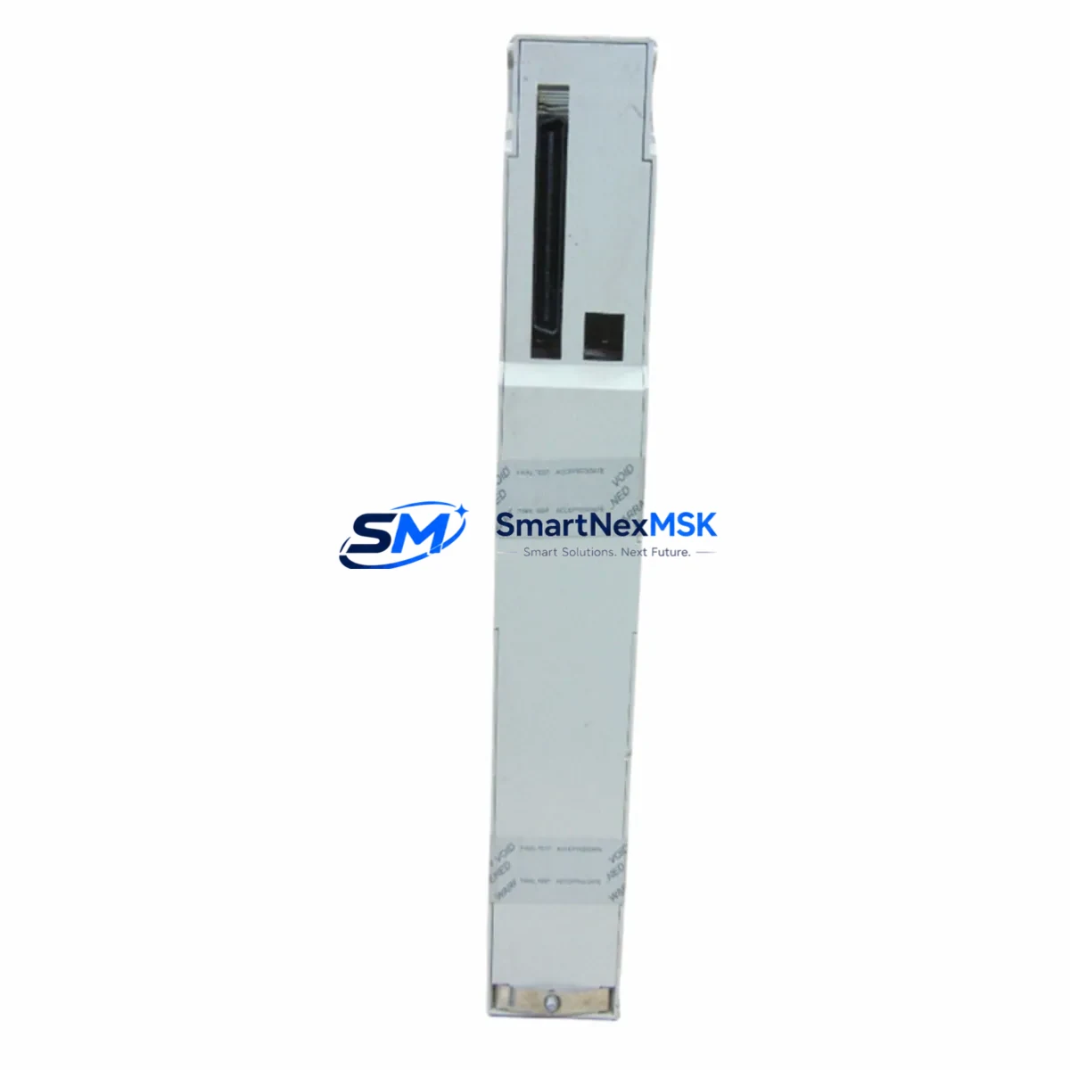
Schneider 140CPS22400 Retrofit-Ready Power Supply for Quantum Control Systems
The Schneider Electric 140CPS22400 is a DC 24V, 8A redundant power supply module engineered for the Modicon Quantum automation platform. As legacy Quantum installations age and original power supply modules approach end-of-life, the 140CPS22400 serves as a verified drop-in replacement that restores full system redundancy without requiring rack redesign, PLC reprogramming, or HMI reconfiguration. Whether you are managing a planned upgrade cycle or responding to an unplanned failure on a critical production line, this module delivers the electrical performance and mechanical compatibility your control cabinet demands.
The 140CPS22400 mounts directly into the Modicon Quantum backplane — including the 140XBP01600 16-slot rack and the 140XBP00600 6-slot rack — and interfaces with the Quantum CPU modules such as the 140CPU65160 and 140CPU67160 without firmware modification. Its 24 VDC input and 8 A continuous output rating match the original power budget of most Quantum control cabinets, making it suitable for systems that also house 140ACI04000 analog input modules, 140DDO35300 discrete output modules, and 140NOE77101 Ethernet communication modules.
Upgrade Compatibility Table
| Parameter | 140CPS22400 Specification | Retrofit Notes |
|---|---|---|
| Input Voltage | DC 24V (18–30V range) | Verify upstream DC bus voltage before installation |
| Output Current | 8A continuous | Audit total I/O module current draw before replacement |
| Redundancy Support | Yes — hot-standby capable | Pair with second 140CPS22400 for full redundancy |
| Rack Compatibility | 140XBP01600, 140XBP00600, 140XBP01000 | Direct slot insertion; no adapter required |
| Communication Interface | Backplane bus (Quantum standard) | No protocol migration required |
| Terminal Wiring | Screw-terminal DC input block | Retain existing wire labels; re-torque to spec (0.5–0.6 Nm) |
| Replacement Candidates | 140CPS22400, 140CPS11420, 140CPS21100 | Confirm output current rating matches original module |
| Commissioning Requirement | No software configuration needed | Power cycle and verify LED status indicators post-installation |
| Warranty | 12 Months | Covers manufacturing defects; includes pre-shipment functional test |
Retrofit Planning for Existing Automation Systems
A successful 140CPS22400 retrofit begins well before the module arrives on-site. Start by auditing the total current consumption of every module installed in the Quantum rack. Add up the draw from all installed I/O modules — including any 140AVI03000 analog voltage input modules, 140DDI35300 discrete input modules, and 140CRP93200 RIO head-end modules — and confirm the aggregate does not exceed the 8A output ceiling of the replacement power supply. If the rack is heavily populated, consider whether a second redundant 140CPS22400 is already installed or should be added as part of the upgrade scope.
Next, document the existing terminal wiring on the DC input block. Photograph the wire routing, label each conductor, and note the torque specification before disconnecting. The 140CPS22400 uses the same screw-terminal input block format as earlier Quantum power supply variants, so re-termination is straightforward — but field wiring errors during power supply swaps are a leading cause of post-retrofit faults. If the control cabinet also houses a 140CPS11420 AC-input power supply in a parallel rack, verify that the DC bus interconnect between racks is correctly rated for the combined load.
For systems that include a 140NOM21100 Modbus Plus network option module or a 140NOE77101 Ethernet TCP/IP module, confirm that the communication links remain active during the power supply swap if a redundant supply is in service. In non-redundant configurations, plan for a controlled shutdown: save the Unity Pro or Concept application program to the programming terminal, note all I/O forcing conditions, and coordinate with the process team to place the line in a safe hold state before removing the module.
If the retrofit scope extends to replacing aging 140CPU65160 processors or migrating I/O to a newer Modicon M580 platform, the 140CPS22400 can serve as an interim power solution while the broader migration is staged across multiple maintenance windows — minimizing capital expenditure in any single outage period.
Downtime Control During System Migration
Minimizing unplanned downtime during a Quantum power supply replacement requires a structured pre-outage checklist and a clear rollback plan. Before the maintenance window opens, upload the current Unity Pro or Concept application to a laptop, verify the program checksum, and confirm that all PLC data blocks and retain variables are backed up. If the system uses a 140CPU67160 hot-standby CPU pair, the standby CPU should assume control before the primary rack is de-energized — this keeps field I/O active and preserves HMI display continuity on any connected Magelis or third-party SCADA screens.
During the swap, keep the replacement 140CPS22400 in its anti-static packaging until the rack slot is ready. Insert the module firmly until the ejector levers click, reconnect the DC input terminals in the documented sequence, and restore power. Observe the module’s RUN and FAULT LEDs: a steady green RUN LED with no FAULT indication confirms the module has passed its internal self-test and is supplying regulated voltage to the backplane. If the FAULT LED illuminates, measure the DC input voltage at the terminal block before assuming the module is defective — input voltage outside the 18–30V window is the most common cause of post-installation faults.
Once the CPU returns to RUN mode, verify all I/O module status in the Unity Pro I/O map, confirm that the 140NOE77101 Ethernet module has re-established its Modbus TCP connections, and release any I/O forces that were applied before the outage. Document the completed swap in the site maintenance log, including the module serial number, installation date, and technician name — this record supports the 12-month warranty claim process if a defect is identified during the warranty period.
Retrofit Support FAQ
Q1: Is the 140CPS22400 a direct drop-in replacement for the 140CPS11420 and 140CPS21100?
The 140CPS22400 is a DC 24V input module, while the 140CPS11420 accepts AC 115V input and the 140CPS21100 accepts AC 115/230V input. They are not electrically interchangeable. Confirm your cabinet’s input power source before ordering. If your existing supply is AC-fed, you will need the correct AC-input variant or an external AC-to-DC converter upstream of the 140CPS22400.
Q2: Does replacing the power supply require re-downloading the PLC program?
No. The 140CPS22400 is a passive power module with no onboard logic or memory. The application program resides in the CPU module (e.g., 140CPU65160 or 140CPU67160) and is unaffected by a power supply swap. After restoration, the CPU will resume execution from its last saved state, provided the DC bus was restored within the CPU’s power-hold time specification.
Q3: What pre-shipment testing is performed on the 140CPS22400?
Each unit undergoes a functional load test at rated output current (8A DC) before shipment. Input voltage regulation, output ripple, and overcurrent protection response are verified. A test report is available upon request. All units are covered by a 12-month warranty against manufacturing defects from the date of shipment.
Q4: Can the 140CPS22400 be used in a redundant power supply configuration?
Yes. The Modicon Quantum platform supports dual power supply redundancy when two 140CPS22400 modules are installed in the designated power supply slots of a compatible rack. In this configuration, if one module fails, the second assumes the full load without interrupting CPU operation or field I/O. Verify that your rack model (e.g., 140XBP01600) supports dual power supply slots before planning a redundant configuration.
© 2026 SMARTNEXMSK. All rights reserved.
Original Source: https://smartnexmsk.com
Contact: [email protected] | +86 18259474341