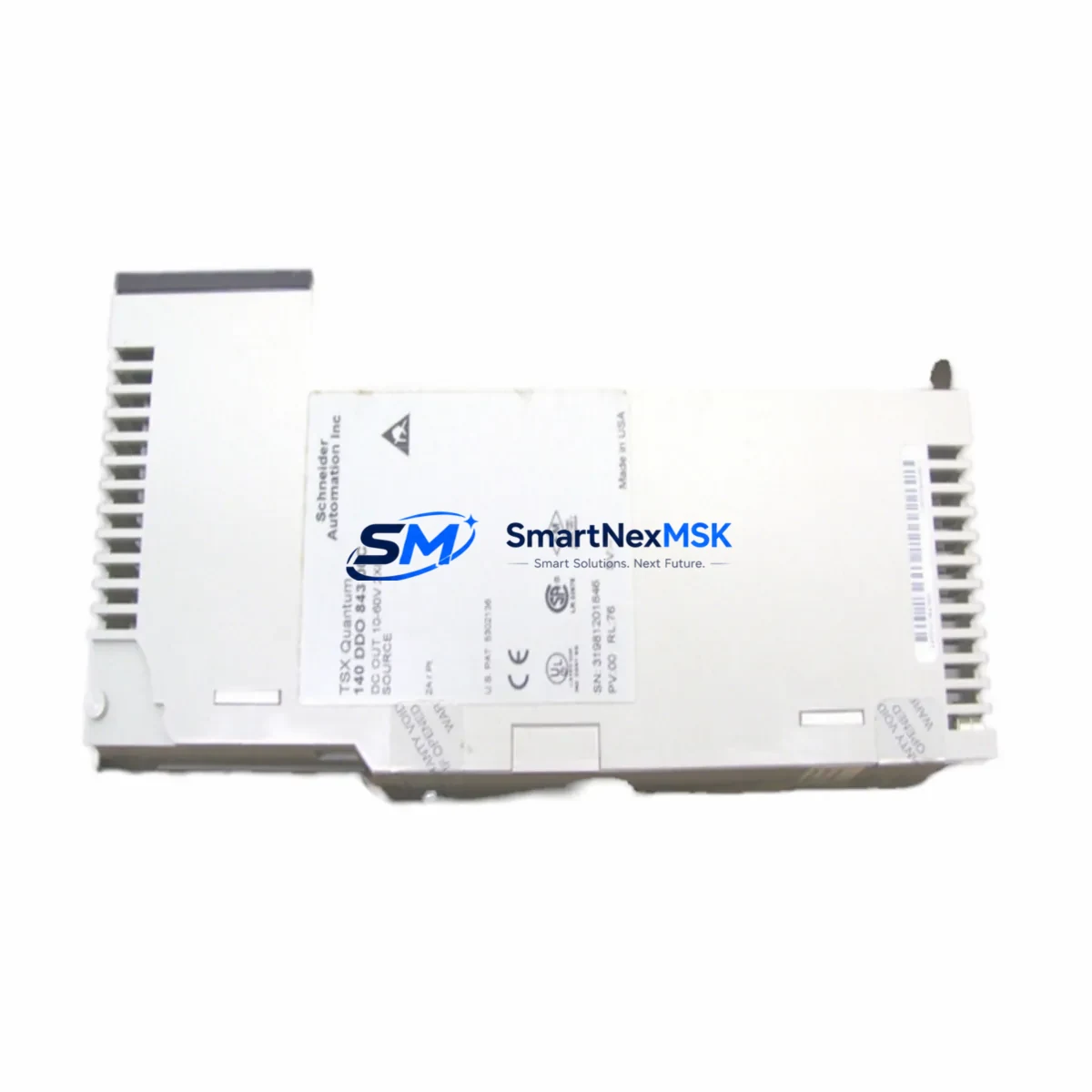
Schneider 140DDO84300 Retrofit-Ready Discrete Output for Quantum Control Systems
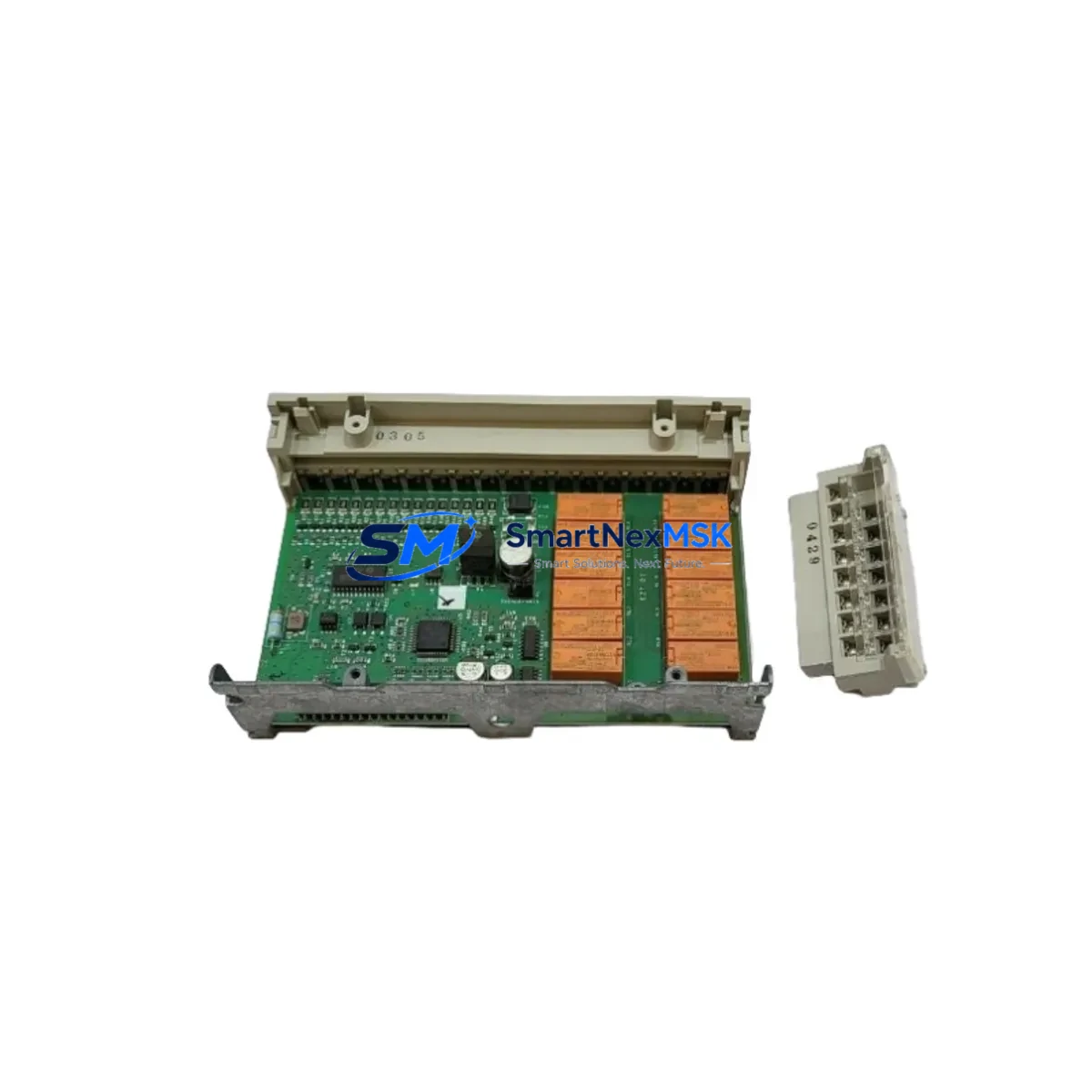
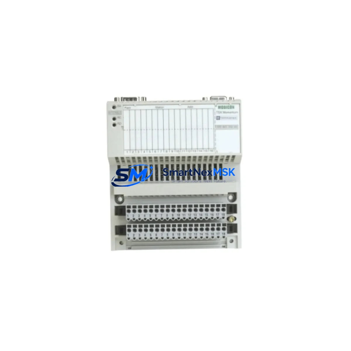
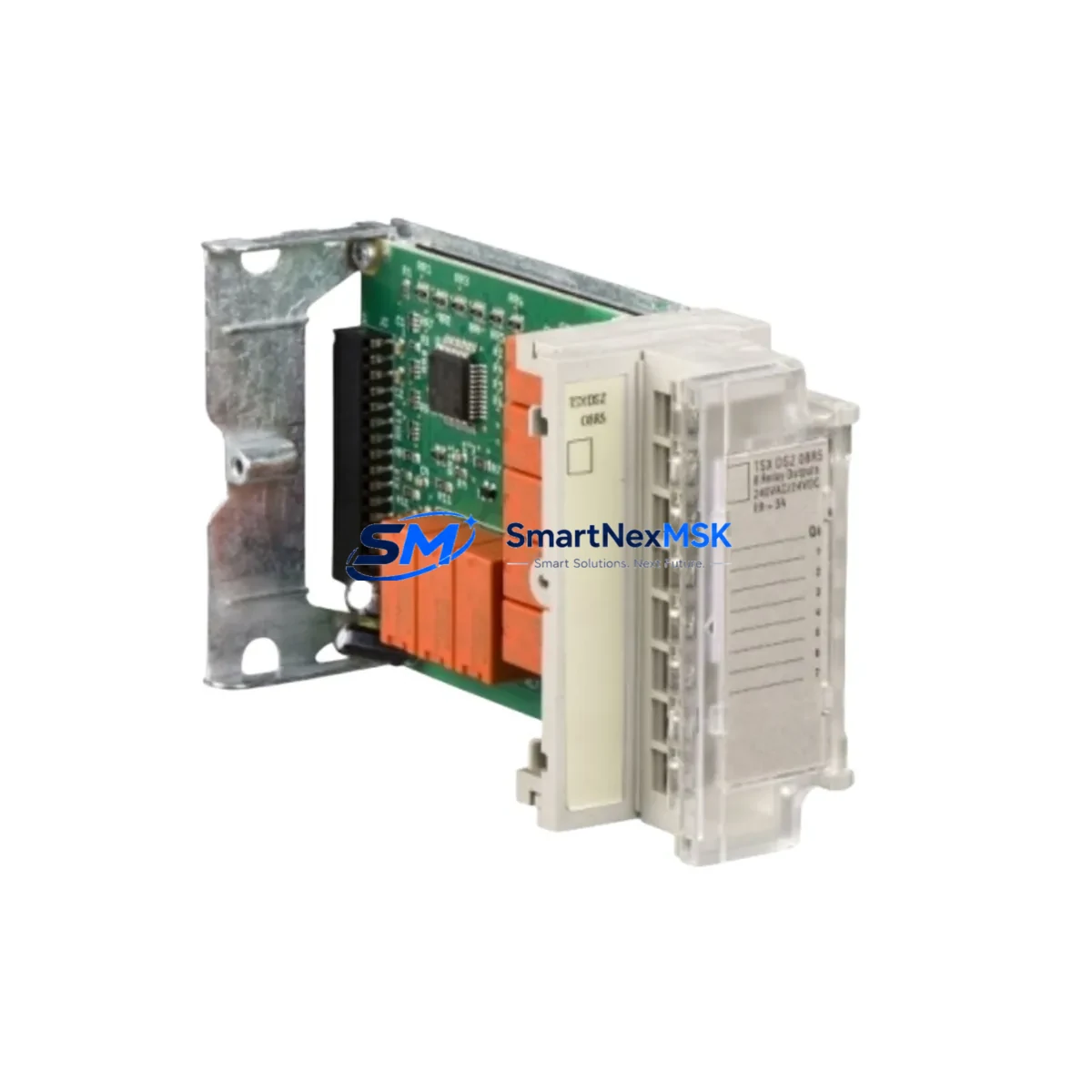
The Schneider Electric 140DDO84300 is an 84-point sourcing discrete output module engineered for the Modicon Quantum automation platform. As legacy Quantum systems approach end-of-life and spare parts become increasingly scarce, the 140DDO84300 remains one of the most sought-after retrofit and replacement components for engineers managing aging discrete control architectures. Whether you are replacing a failed module in a running production line, upgrading a control cabinet to extend operational life, or migrating I/O capacity from an obsolete predecessor, this module delivers the output density and backplane compatibility required for a smooth, low-risk transition.
The 140DDO84300 installs directly into the Quantum backplane — compatible with the 140XBP01600 16-slot rack and the 140XBP00600 6-slot rack — and communicates natively over the Quantum I/O bus without requiring firmware changes or address remapping in most retrofit scenarios. Its 84 sourcing outputs are organized across multiple terminal blocks, and field wiring can typically be re-terminated from the legacy module with minimal modification, provided the original wiring documentation is available. Engineers should verify field device voltage ratings (24 VDC nominal) and current draw per output point before energizing the replacement module.
Power budget verification is a critical first step in any Quantum retrofit. The 140CPS11420 and 140CPS21400 power supply modules each carry defined backplane current limits; adding an 84-point output module to a partially loaded rack may require a power supply audit before commissioning. If the existing power supply is already near capacity, a parallel supply or rack reconfiguration using an additional 140XBP01600 expansion rack may be necessary.
Upgrade Compatibility Table
| Parameter | 140DDO84300 Specification | Retrofit Notes |
|---|---|---|
| Output Type | Sourcing (PNP), 84 points | Verify field device polarity before wiring |
| Output Voltage | 24 VDC nominal | Confirm field supply voltage matches |
| Backplane Interface | Quantum I/O bus (direct slot mount) | Compatible with 140XBP01600 / 140XBP00600 |
| Module Address | Configured via Unity Pro / Concept software | Re-use existing address; verify in I/O map |
| Communication Protocol | Quantum proprietary I/O bus | No protocol migration required for same-rack swap |
| Common Replacement For | 140DDO84300 (same SKU restock), 140DDO88500 | Confirm output count and wiring block compatibility |
| Programming Environment | Unity Pro XL / Concept 2.6+ | No program changes required for direct swap |
| Commissioning | Force output test recommended post-installation | Use Unity Pro diagnostic screen to verify all 84 points |
| Warranty | 12-Month Warranty — tested and verified before shipment | |
Retrofit Planning for Existing Automation Systems
Successful integration of the 140DDO84300 into an existing Quantum control system requires a structured retrofit plan. Begin by documenting the current rack layout, including the positions of the 140CPU67160 or 140CPU65150 processor module, any installed 140NOE77101 Ethernet communication modules, and the existing I/O module assignments. This baseline ensures that the replacement module is inserted into the correct slot and that the Unity Pro I/O configuration reflects the physical installation.
Terminal block wiring is the most time-sensitive task during a live-line retrofit. The 140DDO84300 uses a 40-pin connector interface; if the existing field wiring harness was built for the same module family, re-termination is straightforward. However, if the system previously used a different output module such as the 140DDO88500 (32-point transistor output), the wiring density and connector pinout will differ significantly, and a new wiring harness should be prepared in advance to minimize downtime.
For systems that include 140ACI04000 analog input modules or 140AVO02000 analog output modules sharing the same rack, ensure that the backplane power budget accounts for the combined load. Mixed analog and discrete racks are common in process control applications, and the addition of an 84-point output module increases backplane current draw measurably.
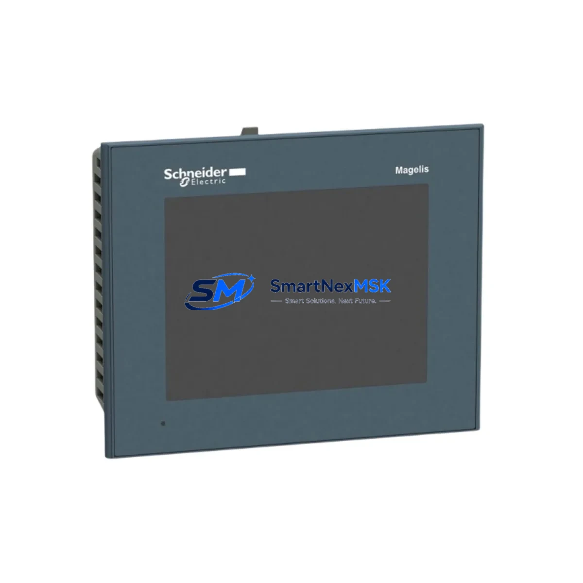
If the control system communicates with an HMI — such as a Magelis XBTGT or a third-party SCADA panel connected via Modbus TCP through the 140NOE77101 — verify that the HMI tag database references output coil addresses that remain valid after the module swap. In most direct-replacement scenarios, coil addresses are preserved, but any rack reconfiguration that shifts slot assignments will require HMI tag updates and a full communications test before returning the system to automatic mode.
Programming cable access is also a consideration during retrofit. The TSXPCX3030 USB-to-serial programming cable or a direct Ethernet connection to the 140NOE77101 allows engineers to upload the existing program backup, verify the I/O configuration, and perform a forced-output test on all 84 points before reconnecting field devices. Always retain a verified program backup on a separate storage medium before beginning any hardware swap.
Downtime Control During System Migration
Minimizing unplanned downtime is the primary concern for any industrial retrofit. For the 140DDO84300, the recommended approach is a hot-standby preparation strategy: pre-configure the replacement module on a bench rack using a 140XBP00600 test rack and a spare 140CPS11420 power supply, verify all 84 output points using a Unity Pro offline simulation, and confirm the module firmware version is compatible with the installed CPU before scheduling the physical swap.
During the actual swap window, follow a structured sequence: place the CPU in Stop mode, de-energize the output field circuits (not the backplane power), extract the failed module, insert the 140DDO84300, restore backplane power, and perform a controlled restart. This sequence protects the original ladder logic and function block program stored in the CPU’s battery-backed RAM — no program download is required for a same-slot, same-model replacement.
For systems where the 140DDO84300 is replacing a different module model (cross-model retrofit), a program modification in Unity Pro will be necessary to update the I/O configuration section. This change should be prepared, simulated, and peer-reviewed offline before the maintenance window. The goal is to reduce the physical swap and recommission time to under 30 minutes, with all field device outputs verified before returning the line to production.
Maintaining control continuity also means ensuring that any Modbus RTU or Modbus TCP polling from upstream SCADA systems is suspended during the swap and resumed only after the CPU has returned to Run mode and all output points have been verified. Coordinate with the control room operator to place the affected process section in manual mode before beginning work.
Retrofit Support FAQ
Q1: Is the 140DDO84300 a direct drop-in replacement for a failed unit of the same model?
Yes. For a same-slot, same-model swap, the 140DDO84300 is a direct replacement. No program changes, address remapping, or wiring modifications are required. The CPU will recognize the module automatically upon restart. Perform a forced-output test on all 84 points to confirm field wiring integrity before returning to automatic mode.
Q2: What wiring and terminal block checks are required before installation?
Verify that the field wiring harness connector matches the 40-pin interface of the 140DDO84300. Check that all field devices are rated for 24 VDC sourcing outputs and that the per-point current draw does not exceed the module’s rated output current. Inspect terminal screws for corrosion or loose connections, and re-torque to specification before energizing.
Q3: How is compatibility with the existing Unity Pro program verified?
Open the Unity Pro project file and navigate to the I/O configuration section. Confirm that the slot assigned to the 140DDO84300 is configured as a discrete output module with 84 points. If the slot was previously occupied by a different module type, update the I/O configuration, rebuild the project, and download to the CPU during the maintenance window. Use the Unity Pro diagnostic screen to verify all output coil states after restart.
Q4: What does the 12-month warranty cover, and how is the module tested before shipment?
Every 140DDO84300 unit supplied by SMARTNEXMSK undergoes a pre-shipment functional test that verifies all 84 output points, backplane interface continuity, and power consumption within specification. The 12-month warranty covers manufacturing defects and functional failures under normal operating conditions. Units are shipped with anti-static packaging and include a test report upon request. Contact [email protected] for warranty claims or technical support.
© 2026 SMARTNEXMSK. All rights reserved.
Original Source: https://smartnexmsk.com
Contact: [email protected] | +86 18259474341