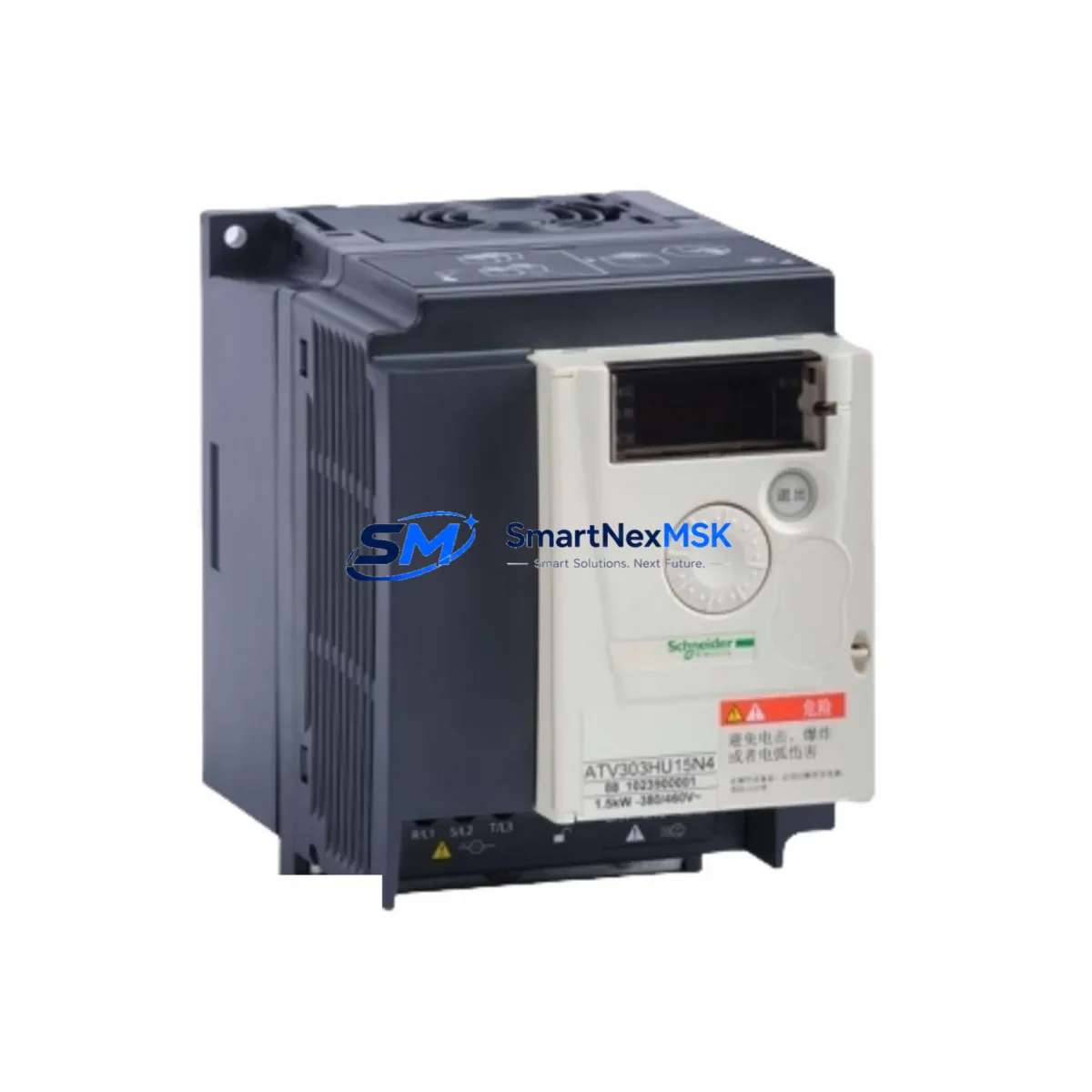
Schneider ATV303H075N4 Retrofit-Ready VFD for Altivar 303 Control Systems
The Schneider Electric ATV303H075N4 is a 0.75 kW (1 HP) three-phase variable frequency drive from the Altivar 303 series, rated for 380–500 V AC input. Designed for pump, fan, and general-purpose motor control applications, this drive is a proven retrofit solution for aging Altivar 303 installations and legacy control panels that require a direct-replacement drive without full system redesign. Whether you are replacing a failed unit on a running production line, upgrading an end-of-life drive in a water treatment facility, or migrating a legacy conveyor system to a more maintainable platform, the ATV303H075N4 provides a reliable, specification-matched upgrade path with minimal downtime.
SMARTNEXMSK maintains verified stock of the ATV303H075N4 sourced from authorized distribution channels. Every unit undergoes pre-shipment functional testing covering input rectification, DC bus charge, IGBT gate drive, and output phase balance. A 12-month warranty is included with each shipment, covering manufacturing defects and drive failure under normal operating conditions.
Upgrade Compatibility Table
| Parameter | ATV303H075N4 Specification | Retrofit Notes |
|---|---|---|
| Power Rating | 0.75 kW / 1 HP | Verify motor nameplate; do not undersize for high-inertia loads |
| Input Voltage | 3-phase 380–500 V AC, 50/60 Hz | Confirm site supply voltage and phase balance before installation |
| Output Current | 2.3 A nominal | Check motor FLA; derate in high-ambient or high-altitude environments |
| Enclosure / Mounting | IP20, DIN rail or panel mount | Matches standard Altivar 303 panel cutout; no mechanical modification required |
| Control Terminals | Analog input (AI1), digital inputs (DI1–DI4), relay output (R1) | Terminal mapping is compatible with ATV303 wiring; verify AI reference signal (0–10 V or 4–20 mA) |
| Communication | Modbus RTU (RJ45) native; optional CANopen | Confirm baud rate, parity, and slave address match existing PLC or SCADA configuration |
| Parameter Backup | Supported via SoMove software or keypad transfer | Back up original drive parameters before removal; restore to new unit to preserve ramp times, PID settings, and fault thresholds |
| Replacement Compatibility | Direct replacement for ATV303H075N4; functional equivalent for ATV303H055N4 (0.55 kW) with motor resizing | Confirm motor cable length; add output choke if cable exceeds 50 m |
| Warranty | 12 Months | Covers manufacturing defects; excludes damage from incorrect wiring or overvoltage events |
Retrofit Planning for Existing Automation Systems
Replacing an ATV303H075N4 in a live automation environment requires careful pre-work to avoid extended downtime and protect the integrity of the existing control logic. Before removing the failed drive, engineers should use Schneider Electric’s SoMove PC software to upload and save the complete parameter set from the original unit — including acceleration and deceleration ramp times, motor thermal protection thresholds, PID reference values, and preset speed configurations. If the original drive is non-functional and parameter recovery is not possible, the replacement unit should be commissioned using the motor nameplate data and the original panel wiring diagram.
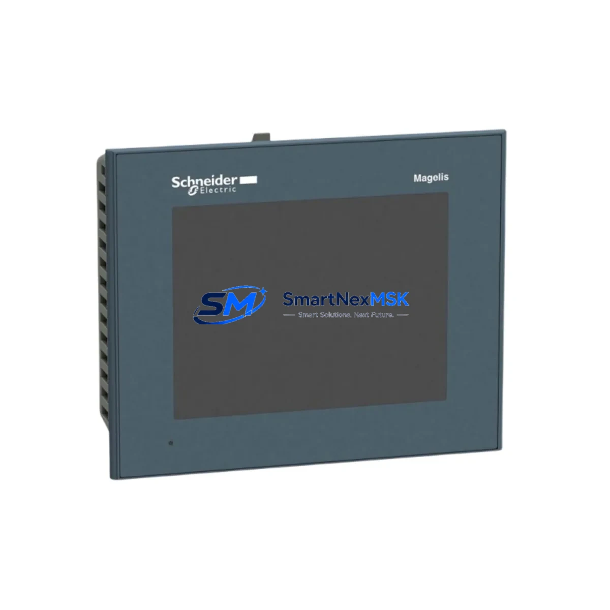
In a typical Altivar 303 retrofit scenario, the control cabinet will also contain a number of associated components that must be inspected and potentially replaced alongside the drive. The 24 V DC control power supply feeding the drive’s logic board and digital input circuit should be load-tested; a degraded power supply is a common secondary cause of drive failure. The Modbus RTU communication link — typically wired through a shielded twisted-pair cable to a Modicon M340 or Modicon M580 PLC — should be verified for correct termination resistance (120 Ω at each end of the bus) and proper shield grounding. If the system uses a Magelis HMIGXU or similar Schneider HMI panel, the drive’s Modbus slave address and baud rate must match the HMI communication parameters exactly to restore operator screen functionality after the swap.
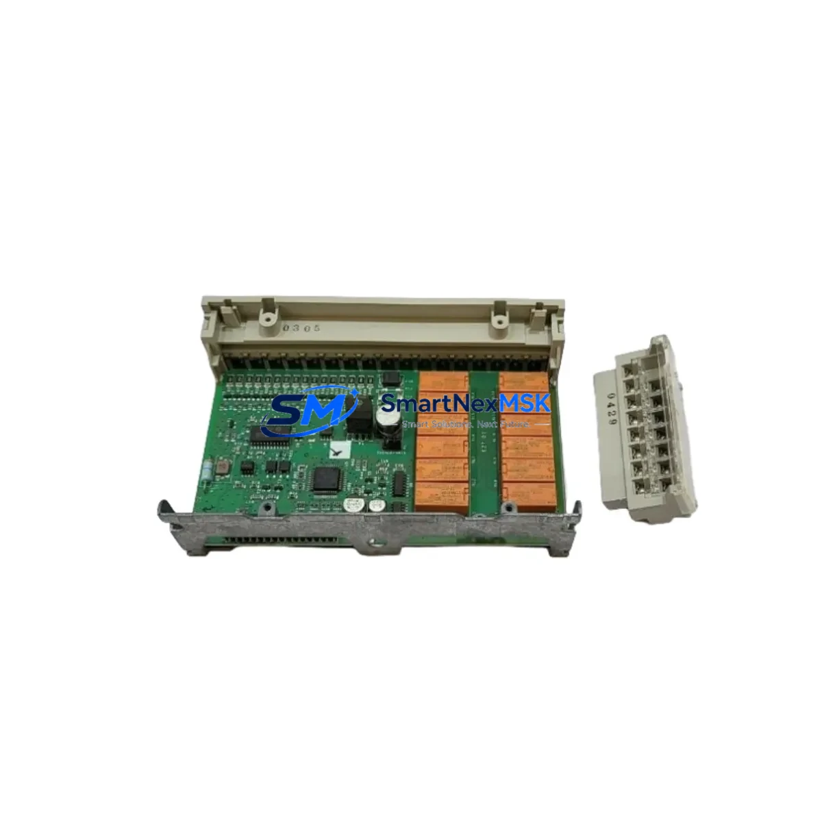
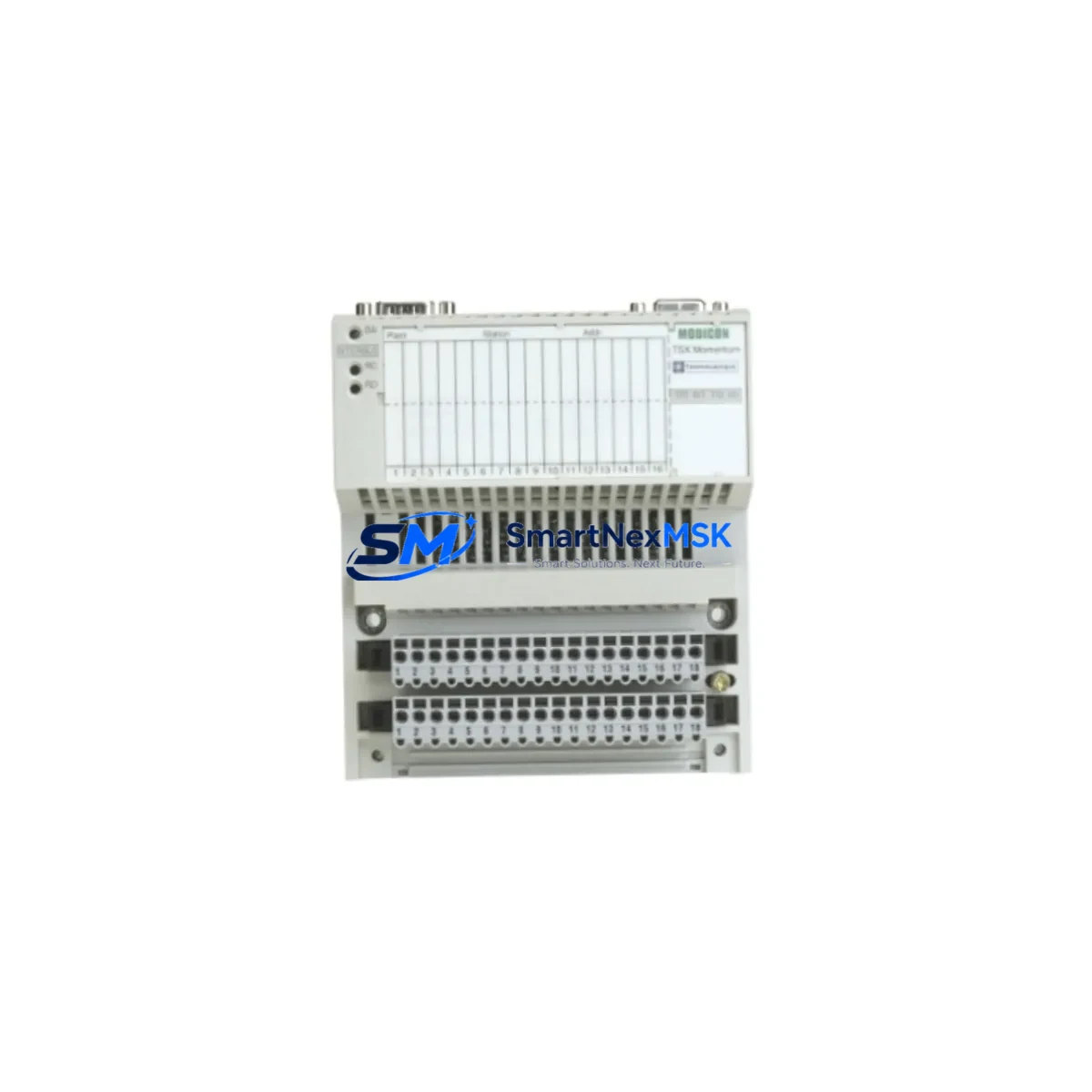
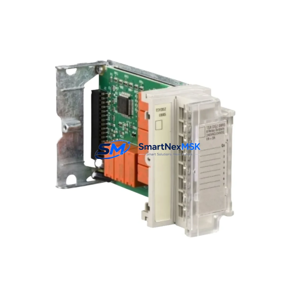
For I/O-intensive applications, the ATV303H075N4 is often installed alongside a TM3 expansion I/O module or a TM2 digital input module connected to the same Modicon controller. These modules handle discrete signals such as run/stop commands, fault acknowledgment, and speed reference selection that are routed through the drive’s digital input terminals DI1 through DI4. Verify that the PLC program’s I/O mapping and the drive’s terminal assignment table are consistent before energizing the replacement unit. In systems where the drive communicates over CANopen rather than Modbus RTU, the CANopen node ID and NMT state machine configuration must be re-entered manually or restored from a saved EDS file.
The drive’s input power wiring should be inspected at the time of replacement. Check the upstream circuit breaker or fuse rating — for a 0.75 kW drive on a 400 V supply, a 6 A type C MCB is typical. Inspect the line reactor or EMC input filter (such as a VW3A4401 line filter) for signs of overheating or capacitor degradation; a failed input filter can cause recurring drive trips on overvoltage or conducted EMI faults. On the output side, verify that the motor cable is correctly shielded and that the shield is bonded to the drive’s PE terminal and the motor frame at both ends. If the installation includes a braking resistor connected to the PA/PB terminals, confirm that the resistor value and wattage rating are within the drive’s specified range.
Downtime Control During System Migration
Minimizing production downtime during an ATV303H075N4 replacement requires a structured swap procedure. The recommended approach is to pre-configure the replacement drive on the bench before the maintenance window begins. Using SoMove software, load the saved parameter file from the original drive into the new unit, verify all settings, and perform a no-load motor rotation test if a test bench motor is available. This pre-commissioning step eliminates the most time-consuming part of the on-site replacement — parameter entry and initial tuning — and reduces the live panel outage to the time required for physical removal, rewiring, and a brief functional verification.
During the panel outage, follow a defined sequence: isolate and lock out the main supply, discharge the DC bus (allow a minimum of 5 minutes after power removal before touching power terminals), photograph the existing terminal wiring before disconnection, remove the failed drive, install the replacement unit, reconnect terminals in the documented order (power first, then control, then communication), and restore power. After energizing, confirm that the drive displays the correct motor parameters, that the Modbus or CANopen communication link is active (check the PLC diagnostic screen or the HMI communication status page), and that the drive responds correctly to a manual run command before returning the system to automatic control.
For critical processes where even a brief outage is unacceptable, consider maintaining a pre-configured spare ATV303H075N4 in the control room with the parameter file already loaded. SMARTNEXMSK can supply pre-tested units with customer-specified parameter files loaded prior to shipment upon request. This approach, combined with a documented wiring reference sheet stored inside the panel door, enables a trained technician to complete a full drive swap in under 30 minutes.
Retrofit Support FAQ
Q1: Is the ATV303H075N4 a direct drop-in replacement for an existing Altivar 303 drive of the same rating?
Yes. The ATV303H075N4 shares the same mechanical footprint, terminal layout, and parameter structure as other units in the Altivar 303 series at the same power rating. Physical installation requires no panel modification. Parameter restoration via SoMove or keypad-to-keypad transfer ensures functional equivalence after replacement.
Q2: How do I verify communication compatibility with my existing PLC before installation?
Confirm the Modbus RTU slave address, baud rate (typically 19200 bps), parity (even), and stop bits (1) configured in the original drive. These settings are stored in the drive’s COM menu. Set identical values in the replacement unit before connecting the RJ45 Modbus cable. Test communication from the PLC diagnostic tool or SCADA system before returning to automatic mode.
Q3: What should I check on the wiring and terminals before powering up the replacement drive?
Verify that L1/L2/L3 input terminals are connected to the correct phases and that the PE ground terminal is bonded to the panel earth bar. On the output side, confirm U/V/W motor connections match the desired rotation direction. Check that all control terminal screws are torqued to specification (typically 0.5–0.6 N·m for the ATV303 control terminal block) and that no bare conductor strands are shorting adjacent terminals.
Q4: What does the 12-month warranty cover, and how is a warranty claim processed?
The 12-month warranty covers manufacturing defects and drive failure under normal operating conditions from the date of shipment. It does not cover damage resulting from incorrect installation, supply voltage outside the rated range, water ingress, or physical impact. To initiate a warranty claim, contact SMARTNEXMSK with the order number, a description of the fault symptom, and any fault codes displayed by the drive. A replacement or repair will be arranged within the warranty period without additional charge for the unit itself.
© 2026 SMARTNEXMSK. All rights reserved.
Original Source: https://smartnexmsk.com
Contact: [email protected] | +86 18259474341