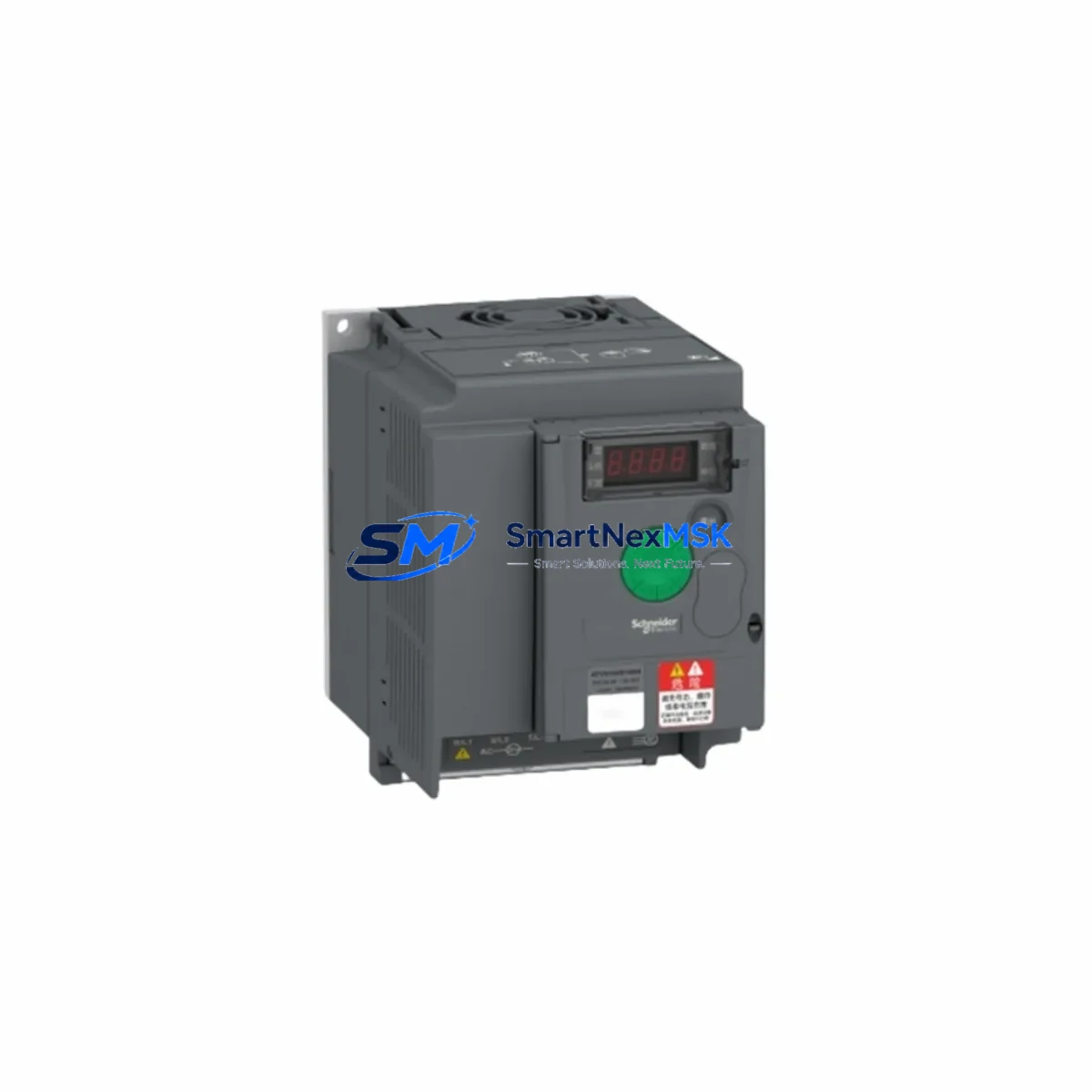
Schneider ATV310HU30N4 Maintenance-Ready Spare Altivar 310: Spare Replacement & Industrial Downtime Risk Control
The Schneider Electric ATV310HU30N4 is a 3kW (4HP), 400V three-phase AC variable frequency drive from the Altivar 310 series — one of the most widely deployed compact VFD platforms in industrial pump, fan, conveyor, and HVAC automation systems. For maintenance engineers managing aging control panels or planning scheduled overhauls, having a verified original spare of the ATV310HU30N4 on hand is a direct line of defense against unplanned production stoppages.
At SMARTNEXMSK, every ATV310HU30N4 unit is sourced from authorized supply chains, electrically tested prior to shipment, and backed by a 12-month warranty. Whether you are executing a like-for-like swap during a planned shutdown or responding to an emergency drive failure on the production floor, this spare is ready for immediate deployment.
Spare Maintenance Table
| Parameter | Specification |
|---|---|
| Part Number / SKU | ATV310HU30N4 |
| Brand | Schneider Electric |
| Series | Altivar 310 |
| Product Type | AC Variable Frequency Drive (VFD) |
| Rated Power | 3 kW (4 HP) |
| Supply Voltage | 380–460V AC, 3-Phase |
| Output Frequency | 0.5–500 Hz |
| Rated Output Current | 7.5 A |
| Control Mode | Sensorless Flux Vector / V/F |
| Protection Rating | IP20 (panel-mount) |
| Communication | Modbus RTU (RJ45) |
| Compatibility | Direct replacement for ATV310HU30N4; compatible with Altivar 310 series wiring and parameter sets |
| Mounting | DIN rail / panel mount |
| Operating Temperature | -10°C to +50°C |
| Country of Origin | China (CN) |
| Warranty | 12 Months — tested before shipment |
| Condition | Original, new or refurbished-to-spec |
| Application | Pumps, fans, conveyors, compressors, HVAC, packaging lines |
| Maintenance Recommendation | Inspect cooling fan, DC bus capacitors, and terminal connections every 12 months or 8,000 operating hours |
Maintenance Planning for Continuous Operation
When a maintenance or procurement engineer schedules replacement of the ATV310HU30N4, the drive itself is rarely the only component requiring attention. A thorough control cabinet inspection during the same maintenance window significantly reduces the risk of secondary failures and repeat downtime events.
Begin with the power supply side: verify that the upstream circuit breaker or GV2 motor protection circuit breaker is correctly rated for the drive’s input current. Check the line reactor or EMC filter (such as the VW3A4401 or VW3A4410 series) for signs of overheating or insulation degradation — these components protect the drive from line transients and should be replaced on the same cycle as the drive in high-cycle environments.
On the output side, inspect the motor cable for insulation integrity, particularly in installations where the cable run exceeds 50 meters. Verify that the output choke or dV/dt filter is intact if one is installed. For the motor itself, check bearing condition and winding resistance before reconnecting to the new drive.
Within the control cabinet, inspect the 24VDC control power supply (such as the Phaseo ABL7 series) that feeds the drive’s logic and I/O circuits. A degraded control power supply can cause intermittent drive faults that are difficult to diagnose. Also check the terminal blocks and wiring ferrules on the control wiring — loose or corroded terminals on the analog speed reference signal (0–10V or 4–20mA) are a common source of erratic speed control after a drive replacement.
If the ATV310HU30N4 is integrated into a Modbus RTU network, verify the RS-485 communication cable continuity and termination resistor status. In multi-drive installations, also inspect the Zelio Logic smart relay or Modicon M221 PLC that issues run/stop and speed reference commands — a faulty digital output module on the controller can damage a newly installed drive within hours of commissioning.
For installations using safety relay modules (such as the Preventa XPSAF or XPSAL series) wired to the drive’s STO (Safe Torque Off) input, test the safety circuit continuity and response time before returning the system to service. Additionally, check any signal isolators or loop-powered transmitters on the analog input circuit — a failed isolator can inject noise or offset into the speed reference, causing the drive to run at incorrect speeds.
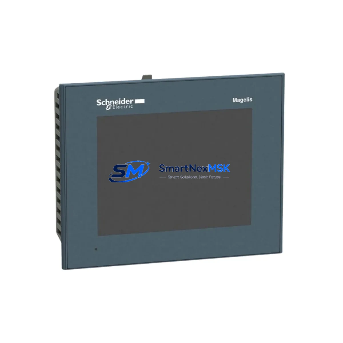
Finally, review the Magelis HMI or remote keypad (VW3A1101 or VW3A1006) if one is installed. Confirm that the parameter backup stored in the HMI or a laptop matches the drive’s required configuration before powering up the replacement unit. Restoring parameters from a saved configuration file eliminates re-commissioning time and reduces the risk of incorrect settings.
Site Replacement Workflow
Step 1 — Isolation & Lockout: De-energize the drive and apply LOTO (Lockout/Tagout) procedure. Wait a minimum of 5 minutes after power-off before opening the drive enclosure to allow DC bus capacitors to discharge. Verify bus voltage with a calibrated multimeter before touching internal components.
Step 2 — Parameter Backup: If the existing drive is still partially functional, use the SoMove software or the VW3A1101 remote keypad to export the full parameter set. Save the file with the machine ID and date for traceability.
Step 3 — Mechanical Removal: Disconnect all power cables (L1/L2/L3 input, U/V/W output, PE ground), control wiring (digital inputs, analog inputs, relay outputs), and the Modbus RJ45 cable. Label all wires before removal. Remove the drive from the DIN rail or panel mounting.
Step 4 — Inspection & Cleaning: Clean the mounting area. Inspect the cabinet for signs of moisture ingress, rodent damage, or carbon tracking from previous fault events. Replace any damaged wiring or terminal blocks before installing the new unit.
Step 5 — Installation of ATV310HU30N4 Spare: Mount the replacement drive. Reconnect all cables in reverse order of removal. Torque all power terminals to the manufacturer’s specification (typically 1.5–2.5 Nm for this frame size). Restore the parameter file via SoMove or keypad.
Step 6 — Pre-Power Checks: Verify supply voltage at the drive input terminals. Confirm motor cable insulation resistance (megger test). Check that all safety interlocks and STO wiring are correctly connected.
Step 7 — Commissioning & Handover: Power up the drive in local control mode first. Run the motor at low speed (5–10 Hz) and verify direction, current draw, and absence of fault codes. Switch to remote/network control and confirm Modbus communication. Document the replacement in the maintenance log and update the spare parts inventory.
Spare Parts Support FAQ
Q1: Is the ATV310HU30N4 spare compatible with my existing Altivar 310 installation without parameter changes?
Yes. The ATV310HU30N4 is a direct form-fit-function replacement for the same part number. If you restore a previously saved parameter file, no re-commissioning is required beyond a functional test. If no backup exists, the factory default parameters are a safe starting point for most standard pump and fan applications.
Q2: How is the spare tested before shipment?
Every ATV310HU30N4 unit dispatched by SMARTNEXMSK undergoes electrical power-on testing to verify DC bus charging, output phase balance, and control logic response. Units that fail any test criterion are quarantined and not shipped. A test record is available upon request for critical applications.
Q3: What is the recommended spare parts stocking strategy for Altivar 310 drives?
For facilities operating more than three ATV310HU30N4 units, we recommend maintaining at least one cold spare on-site. For critical processes (continuous production, water treatment, HVAC), a hot-standby spare in the control room is advisable. Given the Altivar 310 series’ end-of-commercialization status, securing long-term supply through a reliable distributor is strongly recommended to avoid obsolescence risk.
Q4: What does the 12-month warranty cover?
The 12-month warranty covers manufacturing defects and electrical failures under normal operating conditions. It does not cover damage resulting from incorrect installation, overvoltage events, water ingress, or operation outside the rated specifications. Warranty claims are processed with return of the defective unit and a brief fault description. Replacement units are dispatched within 5 business days of claim approval.
© 2026 SMARTNEXMSK. All rights reserved.
Original Source: https://smartnexmsk.com
Contact: [email protected] | +86 18259474341