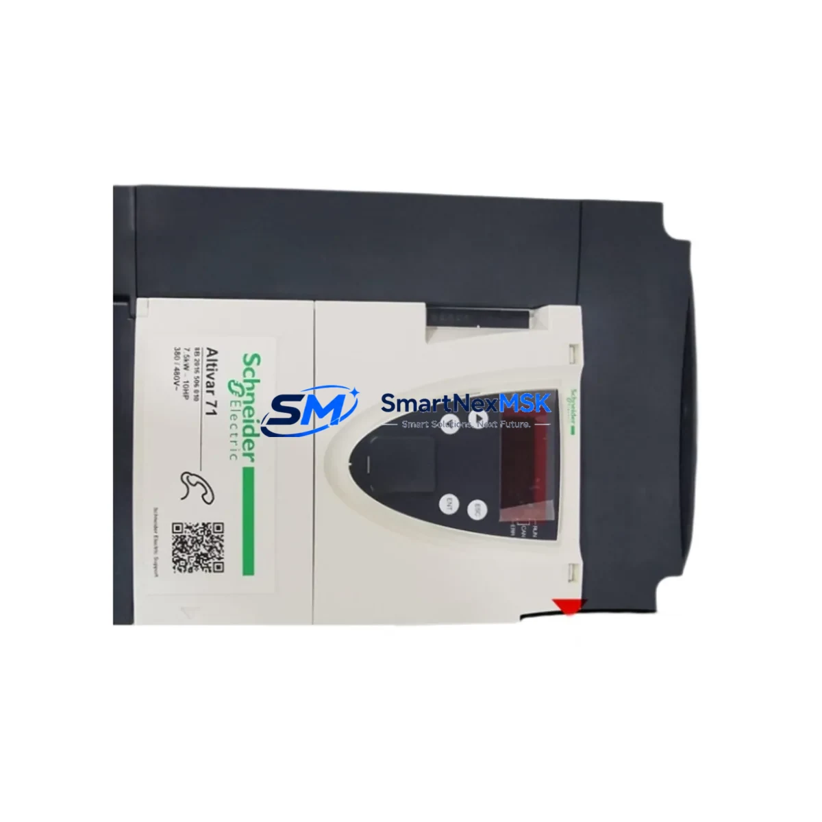
Schneider ATV71HU75N4Z Retrofit-Ready VFD for Altivar 71: Compatible Modernization & Smooth Legacy System Upgrade
The Schneider Electric ATV71HU75N4Z is a 7.5 kW (10 HP) three-phase 380–480 V AC variable frequency drive from the Altivar 71 series, engineered for demanding industrial motor control applications. As legacy Altivar 71 units reach end-of-service life or become unavailable as spare parts, the ATV71HU75N4Z serves as the definitive retrofit-ready replacement — preserving existing wiring infrastructure, communication architecture, and control logic while delivering modern drive performance to aging production lines.
Whether you are managing a planned control cabinet upgrade, responding to an unplanned drive failure, or executing a phased automation modernization program, the ATV71HU75N4Z is designed to minimize engineering rework and reduce commissioning time on the plant floor. Its compatibility with standard Altivar 71 mounting dimensions, terminal layouts, and communication protocols makes it the preferred choice for maintenance engineers and system integrators working within existing panel footprints.
Upgrade Compatibility Table
| Parameter | Details |
|---|---|
| Replacement Target | Altivar 71 series VFDs (ATV71 range), including discontinued variants |
| Power Rating | 7.5 kW / 10 HP, 3-phase 380–480 V AC input |
| Mounting & Form Factor | Compatible with standard ATV71 DIN rail and panel mounting; same footprint as legacy units |
| Terminal Wiring | Power terminals (R/S/T, U/V/W) and control terminals (AI, AO, DI, DO, RO) match original ATV71 layout — no rewiring required in most installations |
| Communication Protocols | Modbus RTU (RS-485), CANopen; optional cards for Profibus DP, DeviceNet, EtherNet/IP via VW3A3xxx option modules |
| Backplane / Rack Interface | Standalone drive; no backplane required. Compatible with Altivar 71 option card slots |
| Parameter Migration | Parameters transferable via SoMove software or ATV71 keypad (VW3A1101); existing parameter files (.stt) are compatible |
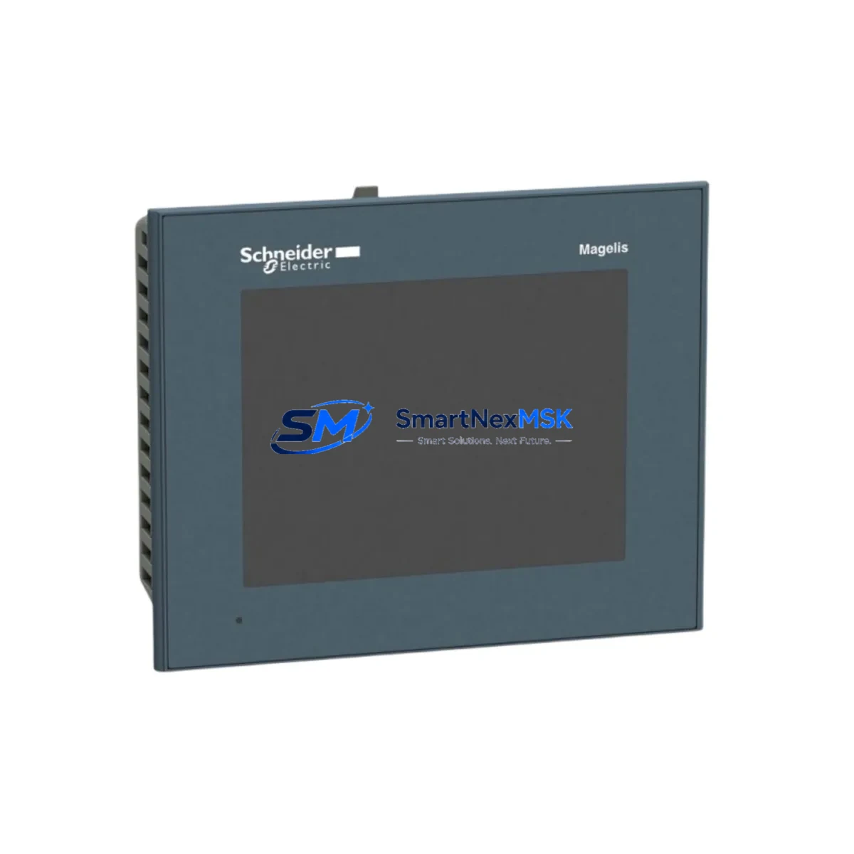
| HMI Compatibility | Compatible with Magelis HMI panels via Modbus; existing HMI screens require no modification if Modbus register mapping is preserved |
| Commissioning Tools | SoMove PC software, VW3A1101 remote keypad, Modbus scanner tools |
| Warranty | 12-Month Warranty — covers manufacturing defects, functional failure under normal operating conditions |
| Replacement Recommendation | Direct drop-in for ATV71HU75N4, ATV71HU75N4S337, and equivalent discontinued part numbers |
Retrofit Planning for Existing Automation Systems
A successful ATV71HU75N4Z retrofit begins well before the drive arrives on site. The first step is a thorough audit of the existing control cabinet: verify the incoming power supply capacity (typically 380–480 V, 3-phase, with sufficient amperage for 7.5 kW continuous load), inspect the condition of the main circuit breaker and input line reactor, and confirm that the existing cable cross-sections meet current IEC wiring standards for the drive’s rated input current of approximately 19 A at 400 V.
Terminal block compatibility is a critical checkpoint. The ATV71HU75N4Z uses the same control terminal strip layout as the original Altivar 71, meaning analog inputs (AI1, AI2), analog output (AO1), digital inputs (DI1–DI6), relay outputs (R1, R2), and the 24 V logic supply are pin-compatible. However, engineers should verify that any existing VW3A3xxx communication option cards — such as the VW3A3310 Profibus DP module or VW3A3316 EtherNet/IP card — are physically transferred from the old unit or replaced with new equivalents, as these cards are not included with the base drive.
For installations using a Modbus RTU network connecting multiple Altivar 71 drives to a Modicon M340 or Modicon M580 PLC, the replacement drive must be assigned the same Modbus slave address as the original unit. This is configured via the drive’s HMI keypad or SoMove software before energizing the network. Failure to match the address will cause communication faults on the PLC side and may trigger safety interlocks.
Where the original system used a CANopen network — common in coordinated multi-axis applications — the ATV71HU75N4Z supports CANopen DS402 drive profile natively. Node ID and baud rate settings must be replicated from the original drive’s parameter backup. If no backup exists, the node ID can often be recovered from the PLC’s CANopen configuration file or the network scanner log.
I/O expansion requirements should also be reviewed during retrofit planning. If the original installation used an ATV71 I/O extension card (VW3A3202) to add additional digital inputs or relay outputs, this card must be reinstalled in the replacement drive’s option slot. Similarly, if a braking resistor was connected to the original drive’s PA/PB terminals for dynamic braking on high-inertia loads, the same resistor can be reconnected to the ATV71HU75N4Z without modification, provided its resistance and power rating remain within the drive’s specification.
For systems where the Altivar 71 communicates with a Magelis XBTGT or XBTGK HMI panel, the existing HMI project screens typically require no modification, as long as the Modbus register addresses used for speed reference, run/stop commands, fault codes, and process feedback remain unchanged. Confirm this by cross-referencing the HMI variable table against the ATV71HU75N4Z parameter list in the programming manual before going live.
Finally, if the control system includes a Twido or Zelio Logic programmable relay handling auxiliary interlocks for the drive, verify that the relay output wiring (R1A/R1B/R1C for fault relay, R2A/R2C for drive running signal) is correctly mapped. These outputs are functionally identical on the ATV71HU75N4Z and require no logic changes in most standard applications.
Downtime Control During System Migration
Minimizing production downtime during a drive replacement is the top priority for most plant maintenance teams. The ATV71HU75N4Z retrofit process is designed to support a rapid changeover — typically achievable within a planned 2–4 hour maintenance window when preparation is thorough.
Pre-shutdown preparation is the most effective downtime reduction strategy. Before the maintenance window opens, use SoMove software to upload and save the complete parameter set from the existing drive via the USB or RS-485 port. Store this backup file (.stt format) on a laptop that will be available on-site during the swap. If the existing drive is already non-functional, attempt to recover parameters from the PLC program comments, the original commissioning report, or the drive’s nameplate data combined with the factory default parameter list.
During the physical swap, label all control wiring before disconnection using numbered ferrules or adhesive cable markers. Photograph the terminal strip from multiple angles. Disconnect power terminals first (after confirming the DC bus has discharged — typically 5–10 minutes after power-off), then remove control wiring. Install the ATV71HU75N4Z in the same mounting position, reconnect control terminals in reverse order, and reattach power cables.
After mechanical installation, restore the parameter backup via SoMove before applying power. Perform a no-load test run at low speed (5–10 Hz) to verify motor rotation direction, analog feedback signals, and relay output states. Confirm Modbus or CANopen communication is established with the PLC before handing control back to the automation system. This structured approach protects the original program logic, preserves HMI screen functionality, and maintains field control continuity throughout the migration.
For critical processes where even a 2-hour window is unacceptable, consider pre-configuring the replacement ATV71HU75N4Z off-line using SoMove and a 24 V auxiliary power supply (connected to the drive’s control terminals) before the maintenance window. This allows full parameter loading and communication testing without energizing the main power circuit, reducing the on-site swap time to under 60 minutes.
Retrofit Support FAQ
Q1: Is the ATV71HU75N4Z a direct replacement for discontinued ATV71HU75N4 and ATV71HU75N4S337 part numbers?
Yes. The ATV71HU75N4Z is the current production variant of the Altivar 71 7.5 kW 400 V drive and is functionally equivalent to the ATV71HU75N4 and ATV71HU75N4S337. Terminal layouts, mounting dimensions, and parameter structures are identical. No mechanical or electrical modifications are required for a direct swap in standard installations.
Q2: Can I transfer my existing parameter file directly to the replacement drive?
Yes, provided the parameter backup was created with SoMove software or the ATV71 keypad (VW3A1101). The .stt parameter file is fully compatible with the ATV71HU75N4Z. After restoring the file, verify motor nameplate data (rated voltage, current, frequency, speed) and auto-tune settings before running under load. If the motor has been changed since the original commissioning, a new auto-tune cycle is recommended.
Q3: What communication wiring changes are needed when replacing the drive on a Modbus RTU network?
No wiring changes are required. The ATV71HU75N4Z uses the same RJ45 Modbus port and RS-485 terminal block as the original Altivar 71. Reconnect the existing Modbus cable, set the slave address and baud rate to match the original drive’s settings, and the PLC will recognize the replacement drive without any program modifications.
Q4: What does the 12-month warranty cover, and how is it claimed?
The 12-month warranty covers manufacturing defects and functional failures under normal operating conditions, including internal component failure, firmware faults, and communication port defects. It does not cover damage caused by incorrect wiring, overvoltage events, physical impact, or operation outside the drive’s rated specifications. To claim warranty service, contact [email protected] with your order number, a description of the fault, and any available fault code data from the drive’s display or SoMove diagnostic log. Replacement or repair will be arranged within the warranty period at no additional cost.
© 2026 SMARTNEXMSK. All rights reserved.
Original Source: https://smartnexmsk.com
Contact: [email protected] | +86 18259474341