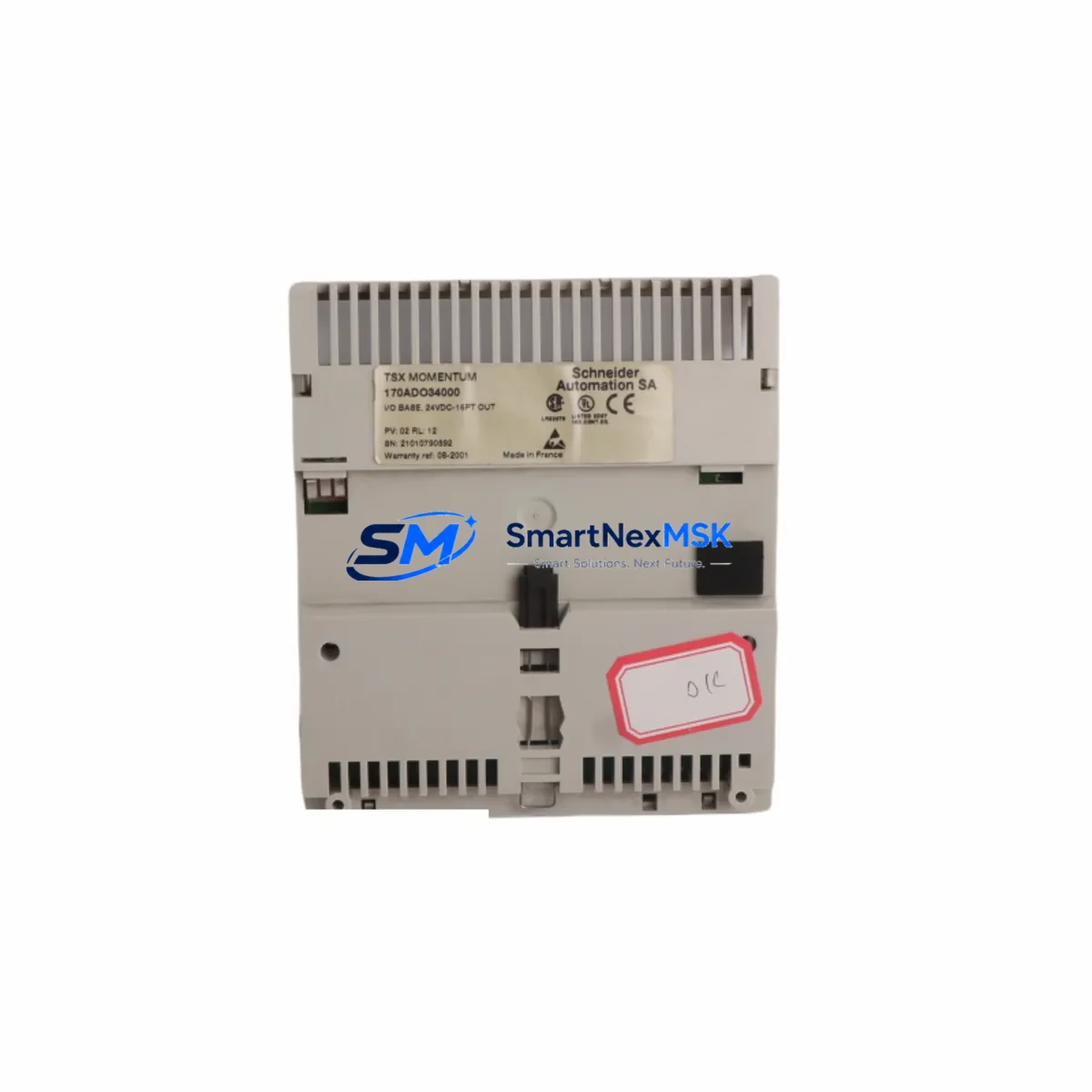
Schneider Electric 170ADO34000 Spare Momentum Automation: Spare Parts Replacement & Industrial Downtime Risk Control
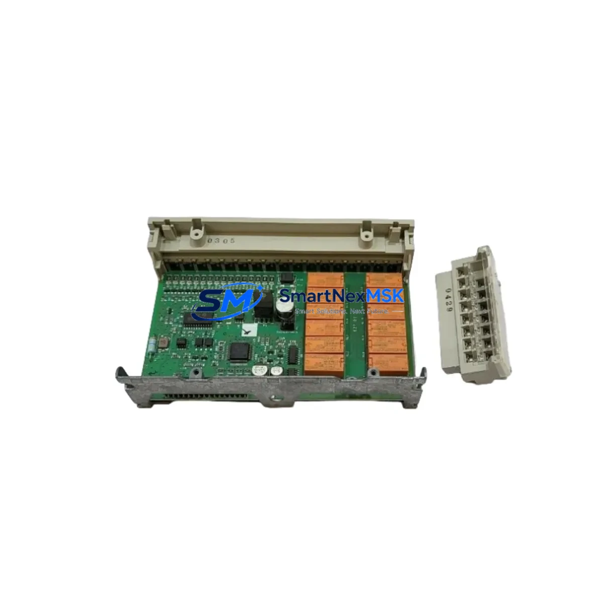
The Schneider Electric 170ADO34000 is a 32-channel, 24 VDC solid-state discrete output module designed for the Modicon Momentum distributed I/O platform. As a maintenance-ready original spare, it is engineered to deliver direct drop-in replacement capability for aging or failed output modules in active production environments — minimizing unplanned downtime and preserving system continuity without requiring re-engineering of the control architecture.
For maintenance engineers managing Momentum-based control cabinets, the 170ADO34000 represents a critical line item in any structured spare parts inventory. Its solid-state output design eliminates mechanical wear, but field failures caused by load-side short circuits, inductive kickback from solenoids and actuators, or sustained overtemperature conditions remain the primary causes of module replacement in industrial facilities. Stocking a verified original unit ensures that when a fault is isolated to this module, the replacement cycle is measured in minutes — not days.
Spare Maintenance Table
| Parameter | Specification |
|---|---|
| Part Number / SKU | 170ADO34000 |
| Brand | Schneider Electric |
| Series | Modicon Momentum |
| Module Type | Discrete Output Module |
| Output Channels | 32 channels |
| Output Voltage | 24 VDC |
| Output Type | Solid-State (Transistor) |
| Output Current per Channel | 0.5 A (typical) |
| Communication Interface | Momentum Backplane Bus |
| Compatible Adapters | 170ANR12090, 170ANR12091, 170ENT11001 (Ethernet), 170PNT11000 (PROFIBUS) |
| Operating Temperature | 0°C to 60°C |
| Mounting | DIN Rail / Panel Mount via Momentum base |
| Origin | France |
| Product Condition | Original New / Tested Surplus |
| Warranty | 12 Months |
| Shipping | Tested before dispatch; ESD-safe packaging |
Maintenance Planning for Continuous Operation
When a 170ADO34000 output module is flagged during a fault isolation routine or scheduled cabinet inspection, experienced maintenance engineers know that the module itself is rarely the only component that warrants attention. A thorough replacement workflow should include inspection of the surrounding electrical circuit to prevent repeat failures and ensure the restored system operates reliably through the next maintenance interval.
Begin by verifying the 24 VDC field power supply feeding the output commons — a degraded or undersized power supply is a frequent root cause of output module stress. If the cabinet uses a 170XTS00100 terminal strip or similar field wiring base, inspect all terminal connections for oxidation, loose crimps, or thermal discoloration. Check the fuse or circuit breaker protecting each output group; blown protection devices indicate a load-side fault that must be resolved before the replacement module is energized.
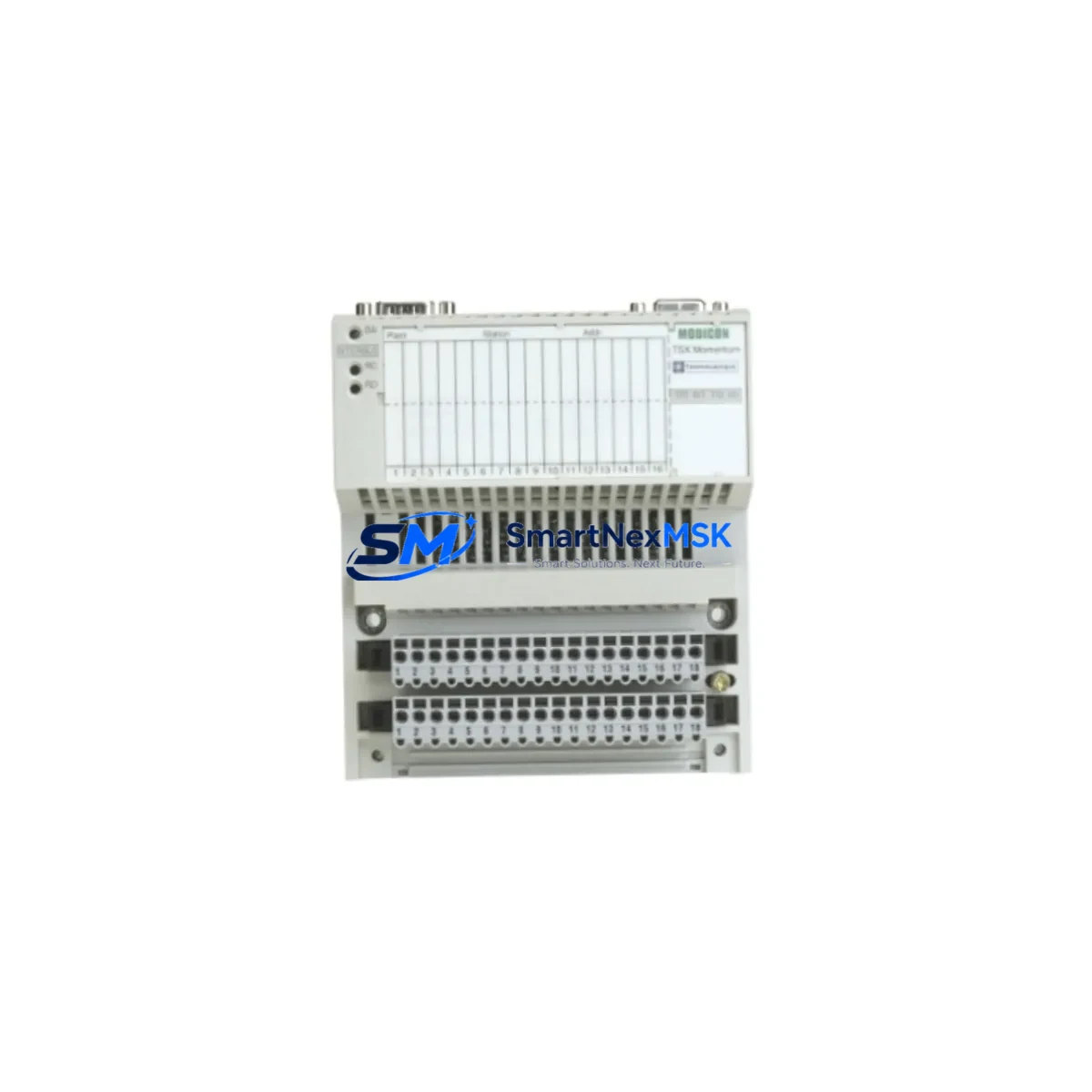
For Momentum systems running on Ethernet, the 170ENT11001 Ethernet communication adapter should be verified for firmware version compatibility and network connectivity before the new output module is brought online. In PROFIBUS-based installations, confirm that the 170PNT11000 PROFIBUS DP adapter is correctly addressed and that the GSD file in the master configuration matches the installed I/O map. A mismatch here will cause the replacement module to appear faulted even when it is electrically healthy.
Inspect adjacent 170ADI34000 discrete input modules in the same Momentum base — shared backplane faults can cause cascading diagnostics that misidentify the output module as the failure source. If the system includes 170AAO92100 analog output modules for valve positioners or variable-speed drives, verify their calibration has not drifted during the fault event. For applications involving inductive loads such as solenoid valves or motor contactors, confirm that freewheeling diodes or RC snubber circuits are installed and functional on each load — their absence accelerates transistor output degradation.
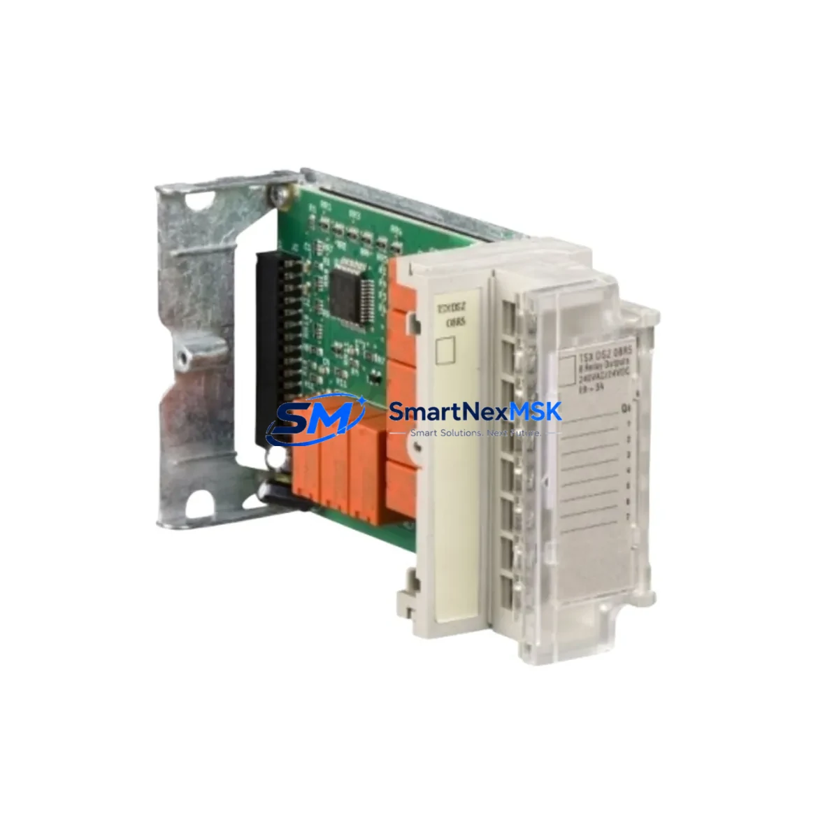
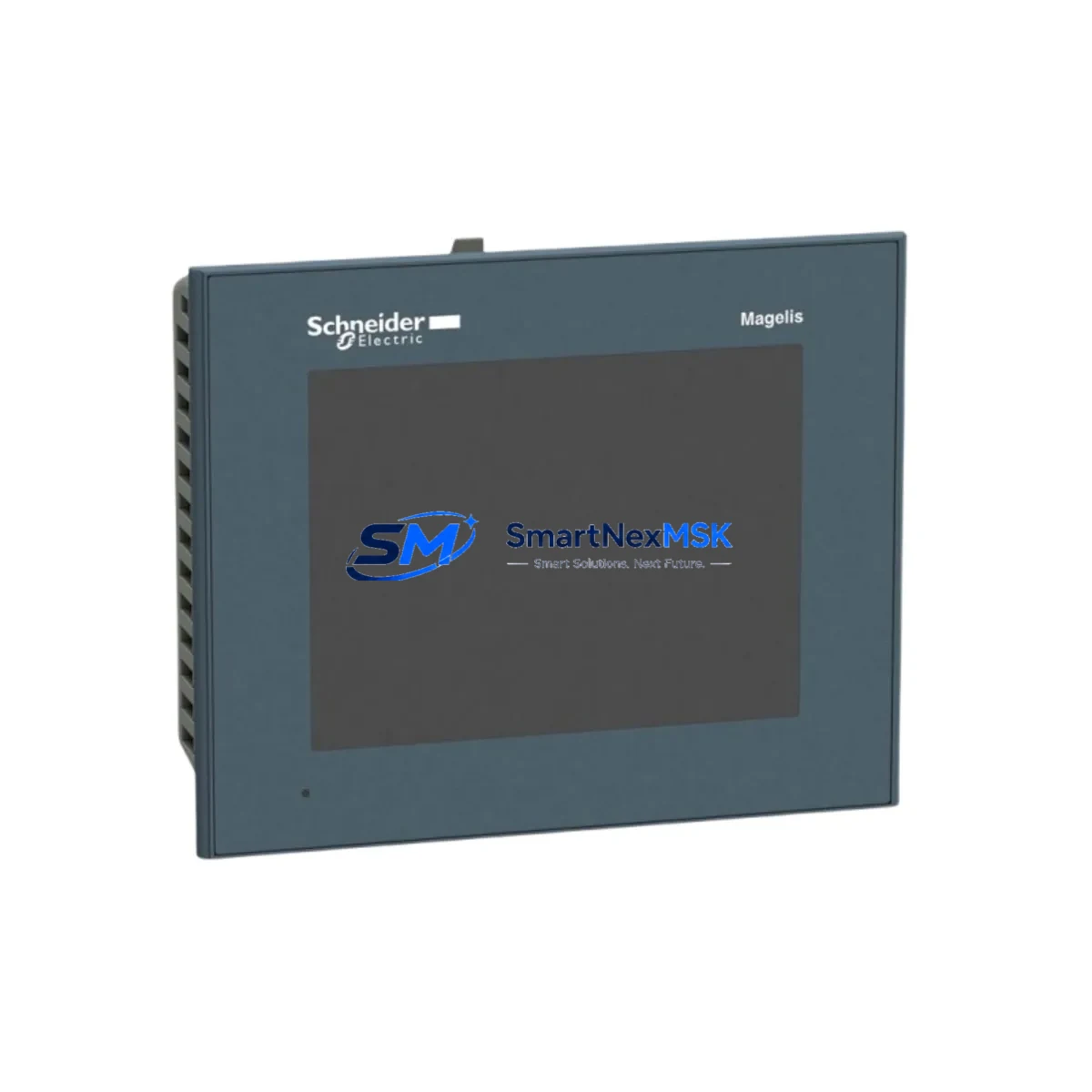
Where signal isolation is required between the PLC output and field devices, check any installed signal isolators or relay output modules (such as the Schneider Electric XMLA series or equivalent DIN-rail isolators) for correct operation. Finally, if the control cabinet includes an XBTGT or Magelis HMI panel, verify that the I/O status display reflects the correct output states after module replacement — this confirms end-to-end system integrity before returning the line to production.
Site Replacement Workflow
Step 1 — Fault Confirmation: Use the Momentum adapter’s diagnostic LEDs or the Unity Pro / EcoStruxure Control Expert software to confirm the 170ADO34000 is the faulted module. Log the fault code and affected output channels before powering down.
Step 2 — Safe Isolation: De-energize the 24 VDC field power supply to the output commons. Do not rely solely on the PLC program to disable outputs — physically isolate field power at the cabinet breaker or fuse block.
Step 3 — Module Removal: Disconnect the field wiring base (terminal strip) from the I/O module body. The Momentum platform allows the wiring base to remain in place while the I/O module is swapped — this eliminates re-wiring and dramatically reduces replacement time. Label all connections if the wiring base must be disturbed.
Step 4 — Replacement Installation: Seat the new 170ADO34000 onto the existing wiring base. Verify the module locks securely and the backplane connector is fully engaged. Restore field power and observe the adapter’s RUN LED for normal status.
Step 5 — Functional Verification: Force each output channel individually from the programming software to confirm correct field device response. Clear all fault logs and return the system to automatic mode. Document the replacement in the site maintenance record.
This workflow is compatible with hot-swap capable Momentum adapter configurations and supports zero-re-engineering replacement — the new module inherits the existing I/O map and PLC program without modification, preserving system compatibility and reducing the risk of commissioning errors in a live production environment.
Spare Parts Support FAQ
Q1: Is the 170ADO34000 still available as a new original part, or only as surplus?
We supply both new original and tested surplus units depending on current stock. All units undergo functional testing and output channel verification before dispatch. Each shipment includes a 12-month warranty covering manufacturing defects and functional failures under normal operating conditions. Contact us to confirm current stock status and lead time.
Q2: How do I verify compatibility with my existing Momentum base and adapter?
The 170ADO34000 is compatible with all standard Momentum I/O bases that accept 32-channel discrete modules. Compatibility depends on the communication adapter installed — confirm your adapter model (Ethernet, PROFIBUS, CANopen, or Interbus) and cross-reference with the Momentum I/O Selection Guide. We can assist with compatibility verification if you provide your adapter part number and PLC configuration details.
Q3: What is your recommended spare parts stocking strategy for Momentum output modules?
For facilities running multiple Momentum bases, we recommend maintaining a minimum of one 170ADO34000 per five installed units as a rolling spare. For critical production lines with no redundancy, a 1:1 hot spare ratio is advisable. Pairing the output module spare with a compatible adapter unit (e.g., 170ENT11001) ensures full module-level replacement capability without waiting for multi-component procurement.
Q4: What testing is performed before shipment?
Each 170ADO34000 unit is powered up and all 32 output channels are individually activated and verified for correct switching response. Insulation resistance and output voltage levels are checked against factory specifications. Units are then packed in ESD-safe anti-static bags with foam cushioning to prevent transit damage. A test report is available upon request for quality-critical procurement processes.
© 2026 SMARTNEXMSK. All rights reserved.
Original Source: https://smartnexmsk.com
Contact: [email protected] | +86 18259474341