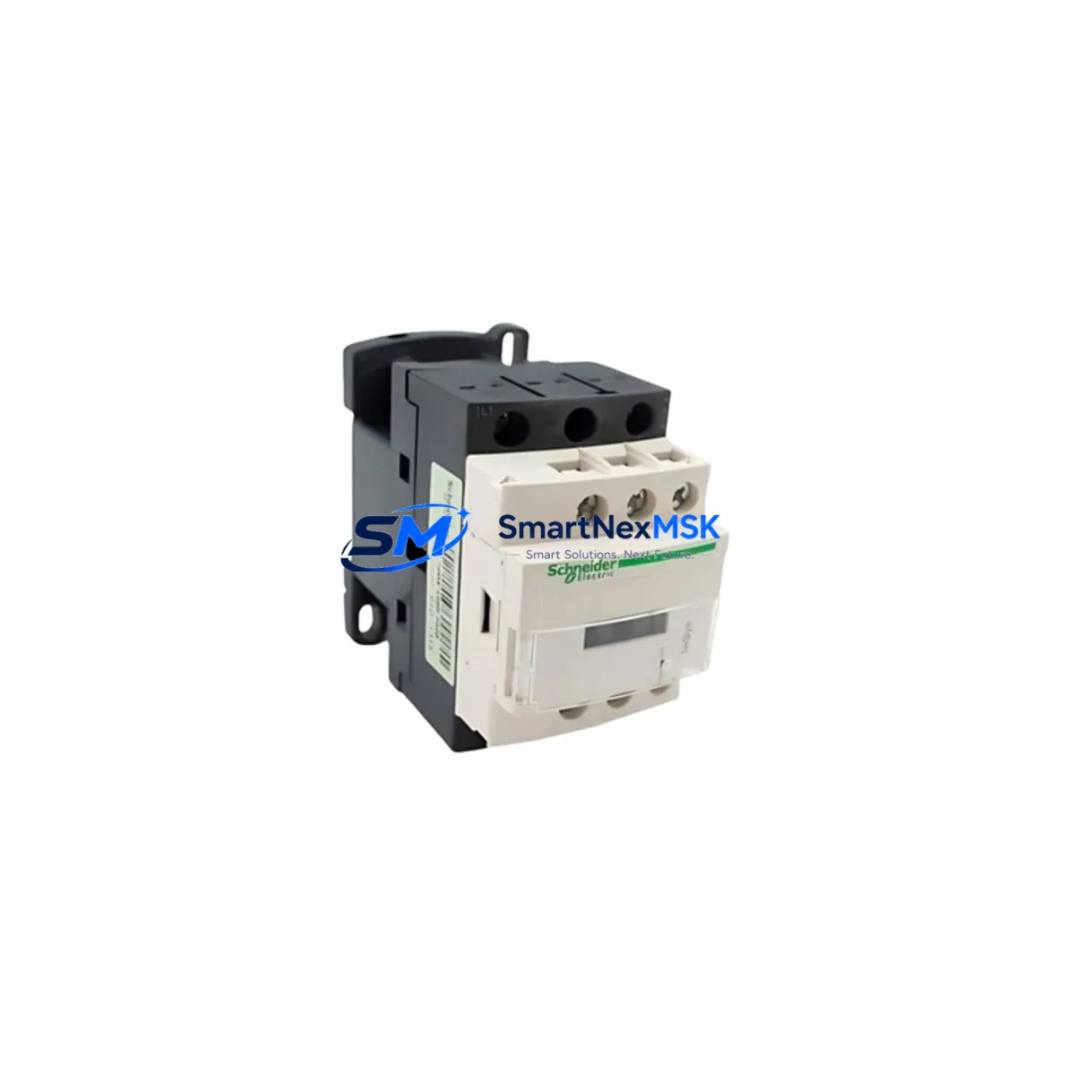
Schneider Electric LC1D12M7C Spare for TeSys D Automation
The Schneider Electric LC1D12M7C is a 3-pole AC contactor from the TeSys D series, rated at 12A with a 220V AC (M7) coil voltage. As a maintenance-ready original spare, it is engineered to deliver direct drop-in replacement capability for aging or failed contactors in motor control centers, control panels, and distributed automation cabinets. For maintenance engineers managing continuous production lines or critical utilities, having a verified LC1D12M7C in stock is a fundamental risk-reduction measure against unplanned downtime.
This contactor is widely deployed in pump control circuits, conveyor drive panels, HVAC motor starters, compressor control cabinets, and light industrial automation systems. Its compact DIN-rail footprint and standardized terminal layout make field replacement straightforward, even under time pressure during emergency shutdowns. The LC1D12M7C is fully compatible with the TeSys D auxiliary contact blocks (LAD4 series), surge suppressors (LAD8N), and mechanical interlocking kits, allowing maintenance teams to restore full circuit functionality without redesigning the control logic.
Spare Maintenance Table
| Parameter | Specification |
|---|---|
| SKU / Part Number | LC1D12M7C |
| Brand | Schneider Electric |
| Series | TeSys D |
| Product Type | 3-Pole AC Contactor |
| Rated Current (AC-3) | 12A @ 400V |
| Coil Voltage | 220V AC / 50–60Hz (M7 coil) |
| Motor Power (400V) | 5.5 kW |
| Pole Configuration | 3NO (main) + 1NO auxiliary |
| Mounting | DIN rail / screw mounting |
| Enclosure Rating | IP20 (open type) |
| Operating Temperature | -5°C to +60°C |
| Compatibility | TeSys D LAD4 auxiliary blocks, LAD8N suppressors, interlocking kits |
| Origin | France |
| Certifications | IEC/EN 60947-4-1, CE, UL, CSA |
| Warranty | 12 Months |
| Condition | Original, New-in-Box |
| Shipping | Tested before dispatch, worldwide delivery |
Maintenance Planning for Continuous Operation
When replacing the LC1D12M7C in the field, a disciplined maintenance engineer will not stop at the contactor alone. The surrounding circuit components should be inspected and, where necessary, replaced as part of the same planned maintenance window to prevent repeat failures and secondary damage.
Start with the TeSys D thermal overload relay (LRD series, e.g. LRD16C or LRD21C), which is typically mounted directly below the LC1D12M7C. A contactor that has failed due to coil burnout or contact welding often indicates that the overload relay has also been subjected to abnormal current events and may have drifted from its calibrated trip threshold. Inspect and test it before re-energizing the circuit.
Next, verify the control power supply feeding the 220V coil circuit. A failing 24VDC-to-220VAC step-up transformer or a degraded Phaseo ABL8 power supply module can cause intermittent coil dropout, leading to repeated contactor cycling and premature contact wear. Measure coil supply voltage under load before declaring the replacement complete.
Check the auxiliary contact block (LAD4BN11 or equivalent) mounted on the LC1D12M7C. These blocks provide feedback signals to the PLC or relay logic and are a common source of false fault indications. If the auxiliary contacts show signs of oxidation or mechanical wear, replace the block alongside the main contactor.
Inspect the control circuit wiring and terminal blocks (Schneider NSYTRV or equivalent DIN-rail terminal strips) connected to the A1/A2 coil terminals and the main power terminals. Loose or corroded terminations are a leading cause of contactor overheating and premature failure. Re-torque all terminals to the manufacturer’s specified values.
If the LC1D12M7C is part of a reversing starter or star-delta starter circuit, also inspect the mechanical interlock kit (LAD9R1) and the paired contactor (often another LC1D12 or LC1D18 variant). Asymmetric wear between the two contactors in a reversing pair is common and should be addressed proactively.
For panels with Modicon M221 or M241 PLC discrete output modules controlling the contactor coil, verify that the output relay or transistor channel driving the LC1D12M7C coil is functioning within specification. A degraded PLC output can cause slow coil energization, resulting in contact bounce and accelerated wear.
Finally, check the surge suppressor (LAD8N or RC snubber) across the coil terminals. A failed suppressor allows voltage spikes to propagate back into the control circuit, potentially damaging PLC I/O cards, signal isolators, or adjacent relay modules. Replace the suppressor if it shows any signs of discoloration or physical damage.
Maintaining a minimum stock of one LC1D12M7C per active motor control circuit, alongside matched overload relays and auxiliary contact blocks, is a recognized best practice for industrial spare parts inventory management in facilities operating TeSys D-based motor control centers.
Site Replacement Workflow
Step 1 — Isolation and lockout: De-energize the panel, apply LOTO (Lockout/Tagout) to the upstream circuit breaker, and verify zero voltage at the contactor main terminals using a calibrated multimeter.
Step 2 — Documentation: Photograph the existing wiring layout, terminal labels, and auxiliary block configuration before disconnecting any wires. This is critical for panels where as-built drawings may be outdated.
Step 3 — Removal: Disconnect the main power cables (L1/L2/L3 and T1/T2/T3), the coil wires (A1/A2), and any auxiliary block wiring. Remove the auxiliary contact block and surge suppressor if they are to be reused. Unclip the contactor from the DIN rail.
Step 4 — Inspection: Inspect the removed LC1D12M7C for contact erosion, coil resistance (measure A1–A2, nominal ~1000–1200Ω for M7 coil), and mechanical operation. Document the failure mode for maintenance records.
Step 5 — Installation: Clip the new LC1D12M7C onto the DIN rail. Reattach the auxiliary contact block and surge suppressor. Reconnect all wiring per the documented layout. Torque all terminals to specification (main terminals: 4–6 Nm; coil terminals: 1.2–1.5 Nm).
Step 6 — Verification: Restore control power only (not main power). Energize the coil via the control circuit and verify audible/tactile engagement. Check auxiliary contact feedback at the PLC or relay panel. Then restore main power and verify motor operation under load.
Step 7 — Record: Update the maintenance management system (CMMS) with the replacement date, new serial number, and any observations. Reset the preventive maintenance interval for this contactor position.
This workflow applies equally to direct-on-line (DOL) starters, reversing starters, and star-delta configurations using the TeSys D platform, ensuring system compatibility is maintained and downtime is minimized to the duration of the physical swap.
Spare Parts Support FAQ
Q1: Is the LC1D12M7C a direct replacement for older TeSys D contactors with the same rating?
Yes. The LC1D12M7C maintains dimensional and electrical compatibility with earlier TeSys D production runs. The terminal layout, DIN-rail clip geometry, and auxiliary block interface are unchanged, allowing direct substitution without panel modification. Always verify the coil voltage (M7 = 220V AC) matches your control circuit before installation.
Q2: How is the LC1D12M7C tested before shipment?
Each unit undergoes coil resistance measurement, mechanical operation check, and contact continuity verification prior to dispatch. Units are shipped in original manufacturer packaging with batch traceability. A 12-month warranty covers manufacturing defects under normal operating conditions.
Q3: What is the recommended spare parts inventory strategy for TeSys D contactors?
For facilities with 10 or more LC1D12M7C units in service, maintaining a minimum of 10% on-hand stock (at least 1–2 units) is recommended. For critical processes with no redundancy, a dedicated emergency spare should be held at the site level, separate from the general warehouse stock. Shelf life for stored contactors is typically 10 years in a dry, temperature-controlled environment.
Q4: Can the LC1D12M7C be used in a star-delta or reversing starter configuration?
Yes. The LC1D12M7C is suitable for use in star-delta starters (typically as the delta or line contactor in a 5.5 kW application) and reversing starter circuits when paired with a mechanical interlock kit (LAD9R1). Ensure that the paired contactor is of the same or compatible current rating and that the interlock is correctly installed to prevent simultaneous energization.
© 2026 SMARTNEXMSK. All rights reserved.
Original Source: https://smartnexmsk.com
Contact: [email protected] | +86 18259474341