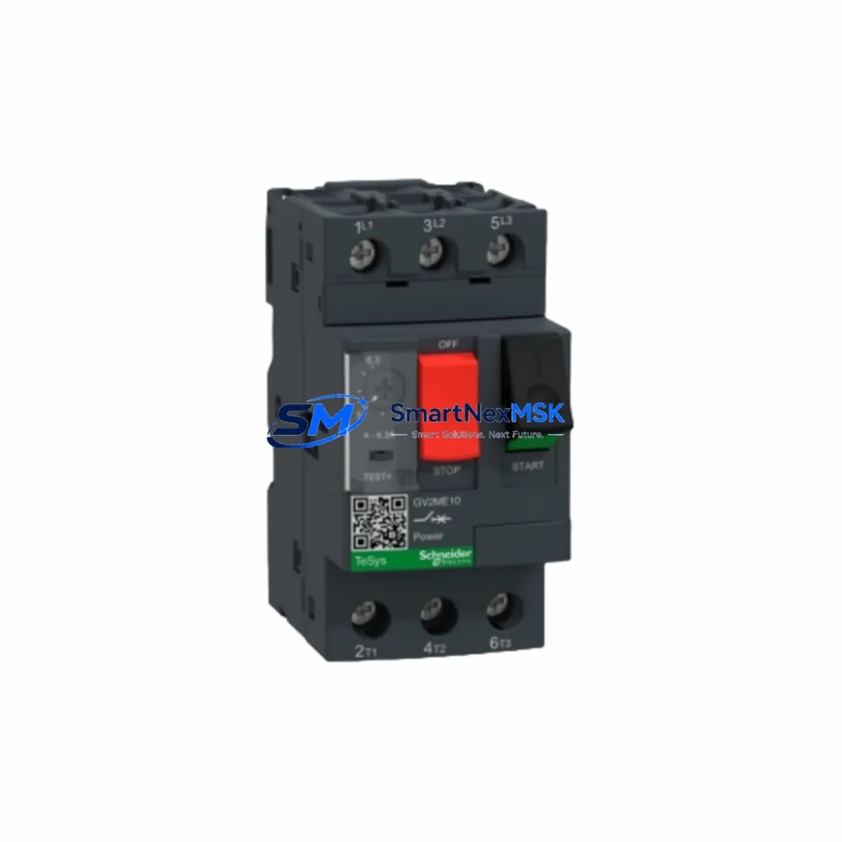
Schneider GV2-ME10C Retrofit-Ready Motor Circuit Breaker for TeSys GV2 Control Systems
The Schneider Electric GV2-ME10C is a 4–6.3A thermal-magnetic motor circuit breaker engineered for the TeSys GV2 series control platform. As legacy motor protection devices reach end-of-life or become increasingly difficult to source, the GV2-ME10C serves as the authoritative retrofit and drop-in replacement solution for aging TeSys GV2 installations across manufacturing lines, pump stations, HVAC control panels, and process automation cabinets. Whether you are upgrading a 1990s-era motor starter panel or restoring a critical production line after an unplanned failure, the GV2-ME10C delivers verified compatibility, predictable installation, and a 12-month warranty backed by in-stock inventory ready for immediate dispatch.
Industrial maintenance engineers and panel builders working on TeSys GV2 retrofit projects will find the GV2-ME10C fully interchangeable with earlier GV2-M and GV2-ME variants in the same ampere frame. The device mounts directly onto standard 35mm DIN rail or onto the GV2-G01 base plate adapter, preserving existing cabinet footprints and eliminating the need for panel re-drilling or busbar relocation. Its compact 45mm width allows side-by-side installation with LC1-D09 or LC1-D12 TeSys D contactors, maintaining the original motor starter assembly geometry that field technicians are already familiar with.
For retrofit projects involving older GV2-M10 or GV2-ME08C units, the GV2-ME10C provides a direct current-range upgrade path. The 4–6.3A adjustment range covers standard 0.75 kW to 1.5 kW three-phase motor loads at 400V AC, making it suitable for conveyor drives, small pump motors, fan starters, and auxiliary machine axes. When replacing a failed GV2-M10 in a running production environment, technicians should verify the existing terminal wiring gauge — typically 1.5 mm² to 4 mm² — and confirm that the upstream iC60N or C60N branch circuit breaker coordination curve remains valid for the new device’s tripping characteristics.
Upgrade Compatibility Table
| Parameter | GV2-ME10C (This Unit) | Legacy GV2-M10 / GV2-ME08C | Retrofit Notes |
|---|---|---|---|
| Current Range | 4–6.3A | 4–6.3A / 2.5–4A | Verify motor FLA; re-set dial after installation |
| Mounting | DIN rail / GV2-G01 base | DIN rail / GV2-G01 base | Direct drop-in; no panel modification required |
| Terminal Type | Screw clamp, 1.5–4 mm² | Screw clamp, 1.5–4 mm² | Reuse existing wiring if conductor is undamaged |
| Auxiliary Contact | Compatible with GV2-AN11 / GV2-AN20 | Compatible with GV2-AN11 / GV2-AN20 | Snap-on auxiliary block reuses without rewiring |
| Communication | Compatible with TeSys U / Modbus via GV2-G250 | Standalone only | Optional upgrade to networked motor management |
| Contactor Pairing | LC1-D09, LC1-D12, LC1-D18 | LC1-D09, LC1-D12 | Confirm contactor coil voltage matches control circuit |
| Installation Standard | IEC 60947-2 / IEC 60947-4-1 | IEC 60947-2 | No re-certification required for like-for-like swap |
| Warranty | 12 Months | N/A (legacy / discontinued) | Covered from date of shipment; includes functional test report |
Retrofit Planning for Existing Automation Systems
A successful GV2-ME10C retrofit begins well before the device arrives on site. During the planning phase, engineers should pull the original panel drawing and cross-reference the existing GV2-M10 or GV2-ME08C position within the motor control center (MCC) or standalone control cabinet. Confirm the upstream branch protection — typically an iC60N C10 or C60N C16 — is correctly coordinated with the GV2-ME10C’s magnetic trip threshold to ensure selective protection is maintained.
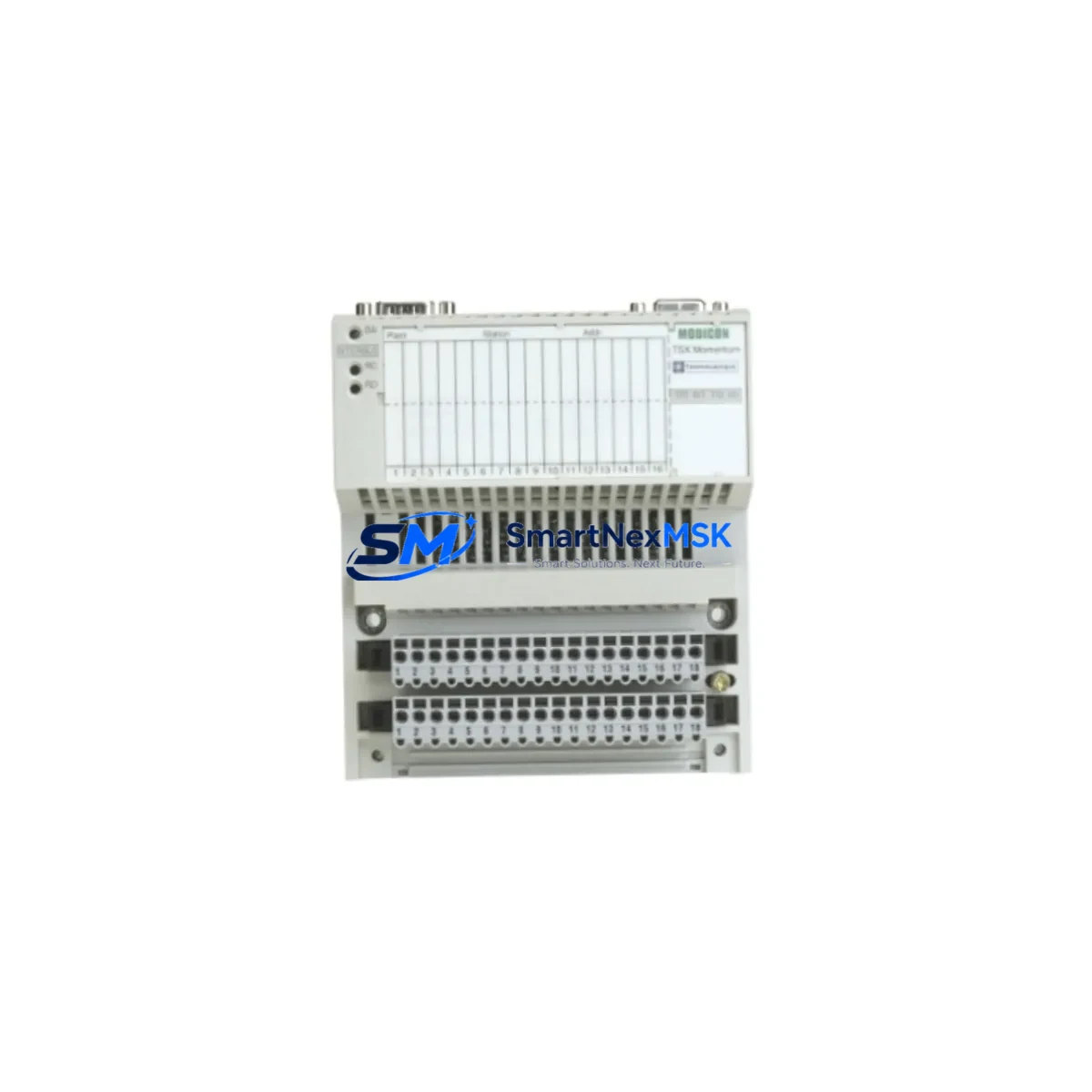
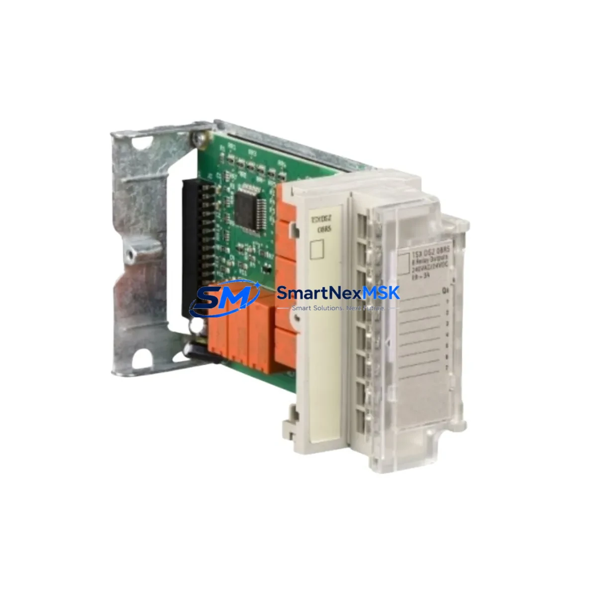
Terminal block layout is a critical checkpoint. In many legacy TeSys GV2 panels, the motor circuit breaker feeds directly into an LC1-D09 or LC1-D12 contactor, with a GV2-AN11 auxiliary contact block providing the fault feedback signal to the PLC input card — often a Modicon M340 or Premium TSX discrete input module. Verify that the auxiliary contact wiring (typically 0.75 mm² control cable) is intact and that the PLC input address assigned to the motor fault signal is documented before disconnecting the old device.
For panels that include a GV2-G250 communication gateway or a TeSys U LUCA controller, the GV2-ME10C integrates into the existing motor management network without firmware changes. If the legacy installation used a standalone GV2-M10 without any communication module, this retrofit is also an opportunity to add a GV2-AN11 auxiliary block and connect the fault output to a spare PLC digital input, improving remote diagnostics capability without replacing the entire motor starter assembly.
Power supply capacity within the control cabinet should be reviewed when multiple motor starters are being upgraded simultaneously. A PHASEO ABL8REM24030 or equivalent 24VDC power supply feeding the control circuit must have sufficient headroom for the contactor coil inrush current during simultaneous motor starts. This is especially relevant in retrofit projects where the number of motor starters in a single cabinet is being increased as part of a broader line modernization effort.
Before final commissioning, perform a functional test sequence: manually trip the GV2-ME10C using the test button, confirm the fault signal reaches the PLC, reset the device, and verify the motor restarts correctly under the control program logic. If the original program used a latched fault routine tied to the GV2 auxiliary contact, confirm the reset logic in the Unity Pro or EcoStruxure Machine Expert project is compatible with the new device’s contact timing.
Downtime Control During System Migration
Minimizing production downtime during a GV2-ME10C swap requires a structured hot-swap protocol. Begin by isolating the affected motor circuit at the upstream branch breaker — do not rely solely on the GV2 itself as the isolation point. Tag out the circuit per LOTO procedures and photograph the existing terminal wiring before disconnection. This documentation is invaluable if the replacement must be reversed or if a second technician completes the job.
The GV2-ME10C’s screw-clamp terminals accept the same conductor sizes as the legacy GV2-M10, so existing cable ferrules can typically be reused. Set the current adjustment dial to match the motor’s nameplate full-load ampere (FLA) rating before energizing. For a 1.1 kW motor at 400V, this is typically 2.8–3.2A; for a 1.5 kW motor, set to 3.5–4.0A — both within the GV2-ME10C’s 4–6.3A range when operating at the lower end of the dial.
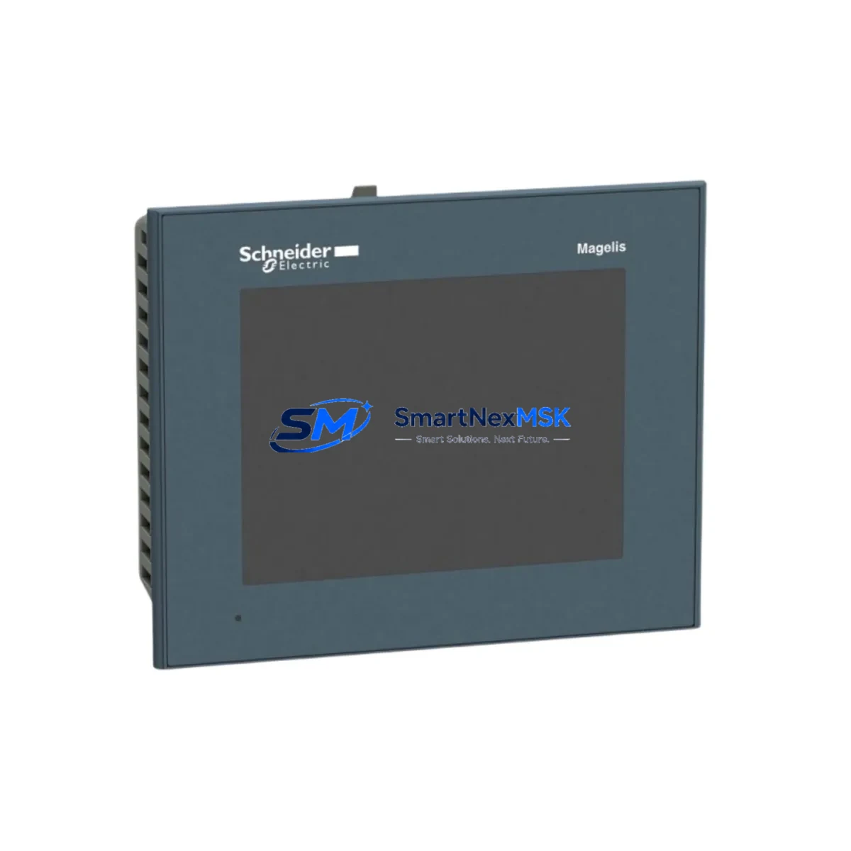
Once the device is installed and wired, restore power to the branch circuit and perform a no-load test before reconnecting the motor. Confirm the PLC fault input reads correctly in the cleared state, then command a motor start from the SCADA or HMI — whether a Magelis HMIGTO panel or a Vijeo Designer-based touchscreen — and verify the motor runs at the expected current draw. Total replacement time for a single GV2-ME10C swap by an experienced technician is typically 20–40 minutes, keeping unplanned downtime well within a single production shift window.
For planned maintenance windows involving multiple motor starters, pre-stage all GV2-ME10C units, pre-set the current dials, and prepare labeled terminal ferrules in advance. This preparation reduces per-unit swap time to under 15 minutes and allows a two-person team to complete a 10-starter cabinet retrofit within a standard 8-hour maintenance shift.
Retrofit Support FAQ
Q1: Is the GV2-ME10C a direct replacement for the GV2-M10 and GV2-ME08C?
The GV2-ME10C is a direct mechanical and electrical replacement for the GV2-M10 in the 4–6.3A current range. It mounts on the same DIN rail footprint, uses the same terminal pitch, and accepts the same GV2-AN11 and GV2-AN20 auxiliary contact blocks. The GV2-ME08C covers a lower current range (2.5–4A); if your motor FLA falls between 4A and 6.3A, the GV2-ME10C is the correct replacement. All units are pre-tested and ship with a functional test report.
Q2: What commissioning steps are required after installation?
After mechanical installation and terminal reconnection, set the current adjustment dial to the motor’s nameplate FLA. Restore branch circuit power, verify the auxiliary contact fault signal at the PLC input, and perform a supervised motor start. Confirm running current is within the set range using a clamp meter. No special software or programming tools are required for the GV2-ME10C itself; however, if you are integrating a new GV2-AN11 auxiliary block for the first time, update the PLC I/O map and HMI fault display accordingly.
Q3: Can the GV2-ME10C be used with Modbus or EtherNet/IP communication?
The GV2-ME10C is a standalone thermal-magnetic device and does not include a built-in fieldbus interface. However, it is fully compatible with the GV2-G250 communication gateway, which provides Modbus RTU connectivity for motor management integration. For EtherNet/IP or Profibus networks, the TeSys U LUCA controller paired with the appropriate communication module is the recommended upgrade path. Contact our technical team for system architecture guidance.
Q4: What does the 12-month warranty cover?
Every GV2-ME10C unit ships with a 12-month warranty covering manufacturing defects, premature tripping outside the rated current range, and auxiliary contact failure under normal operating conditions. Each unit undergoes a pre-shipment functional test — including trip verification and contact continuity check — and ships with a test report. Warranty claims are processed within 5 business days; replacement units are dispatched from stock to minimize your system downtime.
© 2026 SMARTNEXMSK. All rights reserved.
Original Source: https://smartnexmsk.com
Contact: [email protected] | +86 18259474341