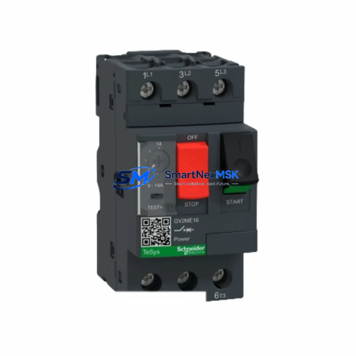
Schneider GV2-ME16C Maintenance-Ready Spare TeSys GV2: Spare Replacement & Industrial Downtime Risk Control
The Schneider Electric GV2-ME16C is a 3-pole thermal-magnetic motor circuit breaker from the TeSys GV2 series, rated for 9–14 A with a breaking capacity of 100 kA at 415 V AC and a maximum operating voltage of 690 V AC. As a critical protection device in motor starter assemblies, control panels, and MCC (Motor Control Center) cabinets, this component is a high-priority spare for maintenance engineers managing continuous production lines, pump stations, HVAC systems, and conveyor drives.
Sourced as an original Schneider Electric spare part, the GV2-ME16C is supplied with full factory testing documentation and ships with a 12-month warranty. Whether you are executing a planned overhaul, responding to an emergency trip, or building a preventive maintenance spare kit, this unit is ready for immediate site installation without additional calibration.
Spare Maintenance Table
| Parameter | Specification |
|---|---|
| SKU / Part Number | GV2-ME16C |
| Brand | Schneider Electric |
| Series | TeSys GV2 |
| Product Type | Motor Circuit Breaker (MCB) |
| Poles | 3-pole |
| Current Setting Range | 9–14 A |
| Rated Operational Voltage | Up to 690 V AC |
| Breaking Capacity (Icu) | 100 kA @ 415 V AC |
| Protection Type | Thermal-magnetic (overload + short-circuit) |
| Mounting | DIN rail or direct mounting |
| Enclosure / IP Rating | IP20 (panel-mounted) |
| Operating Temperature | -25°C to +60°C |
| Compatibility | TeSys GV2 accessories: GV2-AN11, GV2-AF, GV2-AZ, LUB12, LC1-D contactors |
| Origin | France (Original Schneider Electric) |
| Warranty | 12 Months |
| Shipping | Tested & inspected before dispatch; worldwide delivery |
Maintenance Planning for Continuous Operation
When a GV2-ME16C trips or fails in service, the root cause is rarely isolated to the breaker alone. A thorough maintenance response requires inspecting the entire motor starter circuit to prevent repeat failures and reduce mean time to repair (MTTR).
Begin by verifying the upstream power supply. Check the LC1-D09 or LC1-D12 contactor paired with this breaker — worn contact tips or coil degradation are common contributors to nuisance tripping. Inspect the LRD14 or LRD16 overload relay if installed in a separate starter assembly; confirm that the thermal element has not drifted out of calibration after repeated overload events.
Review the GV2-AN11 auxiliary contact block mounted on the breaker — this signal feeds the PLC digital input for motor run/fault status. A faulty auxiliary contact can cause false fault indications in the SCADA or HMI without an actual motor trip. Similarly, inspect the GV2-AF auxiliary contact used for remote signaling or interlocking.
For panels using a Schneider Modicon M340 or M580 PLC, verify that the DI module receiving the GV2 fault signal — such as a BMX DDI 1602 or BMX DDI 3202K — is reading the correct logic state after replacement. A wiring check on the terminal block (e.g., NSYTRV 2.5 or Linergy TB series) should confirm no loose connections introduced during the swap.
If the motor starter cabinet includes a Zelio Logic SR2/SR3 smart relay or a Harmony XB4/XB5 pushbutton station for local start/stop, test these interfaces after reinstalling the GV2-ME16C to confirm the control circuit is intact. For applications with variable-frequency drives (VFDs), check the ATV312 or ATV320 drive fault log to rule out upstream voltage disturbances that may have caused the original trip.
Proactive spare inventory should include at minimum: one GV2-ME16C per motor circuit, one spare LC1-D contactor of the matching frame size, one LRD overload relay, and a set of GV2 auxiliary contact blocks. This kit approach ensures that any single-component failure can be resolved within one maintenance shift without waiting for emergency procurement.
Site Replacement Workflow
Step 1 — Isolation & Lockout/Tagout (LOTO): De-energize the motor circuit at the upstream MCCB or isolator. Apply LOTO per site safety procedure. Confirm absence of voltage with a calibrated tester at the GV2-ME16C line terminals.
Step 2 — Document existing settings: Record the current trip setting dial position on the failed GV2-ME16C (9–14 A range). Photograph terminal wiring before disconnection. Note any auxiliary contact block or alarm module attached.
Step 3 — Remove failed unit: Disconnect line and load cables from terminals. Remove any GV2-AN11 or GV2-AF auxiliary blocks by pressing the release tab. Unclip from DIN rail or remove mounting screws.
Step 4 — Install GV2-ME16C replacement: Mount the new unit on DIN rail. Reattach auxiliary contact blocks. Reconnect line and load cables to the correct terminals (L1/L2/L3 → T1/T2/T3). Set the current dial to match the motor FLA (full-load amperage) per the motor nameplate — typically 80–100% of FLA.
Step 5 — Functional test before re-energization: Verify continuity across all three poles. Confirm auxiliary contact signal at the PLC DI terminal. Re-energize and perform a no-load test run, then a full-load test. Monitor for any immediate trip indication.
Step 6 — Update maintenance records: Log the replacement date, new unit serial number, and trip setting in the equipment maintenance register. Schedule the next inspection per the site’s preventive maintenance calendar.
This workflow minimizes downtime to under 30 minutes for a trained maintenance technician and ensures the replacement is fully compatible with the existing TeSys GV2 system architecture.
Spare Parts Support FAQ
Q1: Is the GV2-ME16C a direct drop-in replacement for older TeSys GV2 units?
Yes. The GV2-ME16C maintains full dimensional and electrical compatibility with all TeSys GV2 series accessories, including GV2-AN11 auxiliary contact blocks, GV2-AF alarm contacts, and GV2-AZ end caps. No wiring modifications are required when replacing a like-for-like unit. If replacing an older GV2-M or GV2-P series unit, verify the current range and terminal pitch before installation.
Q2: How is the unit tested before shipment?
Every GV2-ME16C is inspected for mechanical operation (handle travel, trip mechanism), contact resistance across all three poles, and auxiliary contact continuity prior to packaging. Units are shipped in original or equivalent anti-static protective packaging with a test record. The 12-month warranty covers manufacturing defects and premature failure under normal operating conditions.
Q3: What is the recommended spare inventory strategy for this part?
For facilities with 5 or more motors protected by TeSys GV2 breakers, we recommend maintaining a minimum of 2 units of each current range in stock. The GV2-ME16C (9–14 A) is one of the most commonly deployed ranges for 3–7.5 kW motors at 400 V. Pairing it with a spare LC1-D12 contactor and LRD14 overload relay creates a complete motor starter spare kit that covers the majority of emergency replacement scenarios.
Q4: Can you support long-term or blanket purchase orders for this part?
Yes. We support scheduled delivery agreements, blanket POs, and annual supply contracts for the GV2-ME16C and related TeSys GV2 components. Long-term supply arrangements include priority stock reservation, fixed pricing for the contract period, and dedicated account support. Contact our sales team to discuss volume pricing and delivery schedules tailored to your maintenance planning cycle.
© 2026 SMARTNEXMSK. All rights reserved.
Original Source: https://smartnexmsk.com
Contact: [email protected] | +86 18259474341