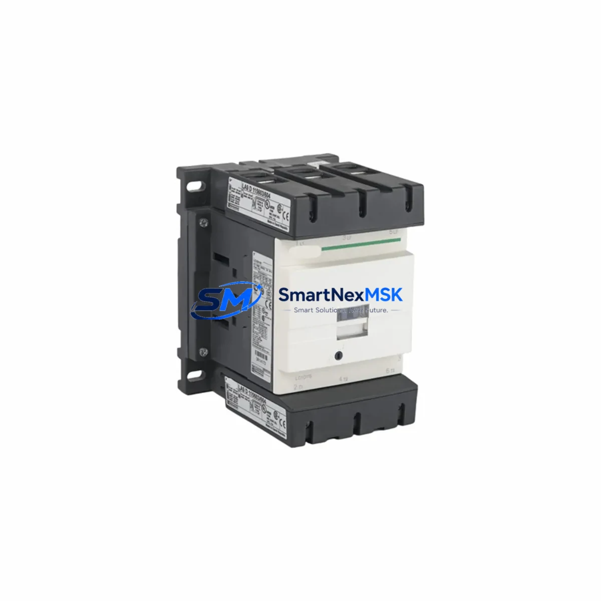
Schneider LC1D150M7C Maintenance-Ready Spare TeSys D Automation
The Schneider Electric LC1D150M7C is a 150A 3-pole electromagnetic contactor from the TeSys D series, designed for heavy-duty motor control and power switching in industrial automation systems. With a 220V AC (M7) coil voltage and IEC-rated performance, this contactor is a critical component in motor control centers (MCCs), variable frequency drive bypass circuits, compressor panels, and high-current distribution boards. Sourced as an original Schneider Electric spare, the LC1D150M7C is tested, serialized, and shipped with a 12-month warranty — making it the preferred choice for maintenance engineers managing planned shutdowns, emergency replacements, and long-term spare parts inventory.
For maintenance and procurement engineers, having the LC1D150M7C pre-positioned in your spare parts cabinet is essential. Contactor failure in a 150A motor circuit typically results in immediate production stoppage. The TeSys D platform is widely deployed across water treatment, cement, mining, oil & gas, and heavy manufacturing — environments where downtime costs far exceed the cost of a stocked spare. This listing supports fast replacement, compatibility-verified delivery, and long-term supply continuity for aging TeSys D installations.
Spare Maintenance Table
| Parameter | Specification |
|---|---|
| SKU / Part Number | LC1D150M7C |
| Brand | Schneider Electric |
| Series | TeSys D |
| Product Type | 3-Pole Electromagnetic Contactor |
| Rated Current (Ie) | 150A AC-3 |
| Coil Voltage | 220V AC 50/60Hz (M7) |
| Poles | 3 Main + 1 NO Auxiliary |
| Rated Operational Voltage | Up to 690V AC |
| Motor Power (400V) | 75 kW |
| Mounting | DIN Rail / Panel Mount |
| Standards | IEC 60947-4-1, CE |
| Origin | France |
| Compatibility | TeSys D Series; replaces LC1D150 variants with M7 coil |
| Application Environment | Industrial panels, MCC, motor starters, bypass circuits |
| Maintenance Recommendation | Inspect contact wear every 12 months or 500,000 operations |
| Warranty | 12 Months |
| Condition | Original, New-in-Box |
| Lead Time | Ships within 3–5 business days |
Maintenance Planning for Continuous Operation
When replacing the LC1D150M7C in the field, a thorough inspection of the surrounding electrical circuit is essential to prevent repeat failures and ensure system reliability. Maintenance engineers should begin by verifying the coil supply voltage at the control circuit terminals — a degraded 220V AC supply or excessive voltage fluctuation is a leading cause of premature coil burnout. Check the associated LC1D150 overload relay (such as the LRD series thermal overload relay) for correct trip class setting and reset condition before re-energizing the motor circuit.
Inspect the auxiliary contact block (LAD8N11 or equivalent) mounted on the contactor for contact continuity and mechanical wear. If the LC1D150M7C is part of a star-delta or reversing starter configuration, the interlocking contactors — typically LC1D80 or LC1D115 — should be checked simultaneously for contact erosion and coil integrity. The control wiring terminal block (such as the NSYTRV series) should be inspected for loose connections, oxidation, and correct torque on all power terminals, particularly at the T1/T2/T3 output lugs carrying 150A load current.
For panels using Schneider TeSys D contactors in conjunction with a Modicon M340 or M580 PLC, verify that the digital output module (such as the BMX DDO 3202K or BMX DDM 16022) controlling the coil circuit is functioning correctly and that the output relay or transistor is not degraded. If the system uses a Preventa XPS safety relay for motor protection, confirm that the safety circuit is intact and that the LC1D150M7C replacement does not alter the safety category rating of the installation.
Additionally, inspect the upstream circuit breaker — typically a Compact NSX250 or NSX400 — for correct trip settings and contact condition. Fuse holders and NH fuse links in the power distribution section should be checked for signs of thermal stress. If the panel includes a Zelio Logic smart relay or a Magelis HMI panel for local motor control, verify that the control logic and status feedback wiring to the new contactor are correctly mapped before returning the system to service.
Site Replacement Workflow
Step 1 — Isolation & Lockout: Isolate the motor circuit using the upstream disconnect switch or circuit breaker. Apply LOTO (Lockout/Tagout) procedure. Verify absence of voltage on all three phases at the contactor input terminals using a calibrated voltage tester.
Step 2 — Documentation: Photograph the existing wiring layout, terminal labels, and auxiliary contact connections before disassembly. Record the coil voltage marking and any auxiliary block part numbers for cross-reference.
Step 3 — Removal: Disconnect all power and control wiring. Remove the overload relay if attached. Unscrew the contactor from the DIN rail or panel mounting plate. Note the orientation of any mechanical interlock bridges if present.
Step 4 — Verification: Confirm the replacement LC1D150M7C matches the original in coil voltage (M7 = 220V AC), pole configuration (3P), and auxiliary contact arrangement. Check that the overload relay LRD range is compatible with the new contactor frame.
Step 5 — Installation: Mount the new LC1D150M7C. Reconnect all power terminals to the correct torque specification (refer to Schneider installation sheet for Nm values). Reconnect control wiring and auxiliary contacts. Reattach the overload relay.
Step 6 — Testing: Before re-energizing, perform a continuity check on the main contacts and coil circuit. Energize the control circuit and verify coil pull-in. Perform a no-load test followed by a loaded motor start. Confirm overload relay is correctly set to motor FLA.
Step 7 — Return to Service: Remove LOTO. Document the replacement in the maintenance log with date, technician name, and new part serial number. Update the spare parts inventory to trigger reorder of the consumed LC1D150M7C unit.
Spare Parts Support FAQ
Q1: Is the LC1D150M7C compatible with my existing TeSys D overload relay and auxiliary blocks?
Yes. The LC1D150M7C is fully compatible with the TeSys D accessory ecosystem, including LRD thermal overload relays, LAD8N11 auxiliary contact blocks, and LA4 suppressor modules. Always verify the overload relay current range matches the motor FLA before installation.
Q2: What is the recommended spare parts stocking strategy for the LC1D150M7C?
For critical motor circuits (pumps, compressors, conveyors), we recommend maintaining a minimum of one LC1D150M7C per installation site. For facilities with multiple TeSys D contactors in the same current range, a 5–10% buffer stock is standard practice. Long lead times from OEM channels make pre-stocked spares essential for emergency downtime recovery.
Q3: How is the LC1D150M7C tested before shipment?
Each unit undergoes coil resistance verification, main contact continuity check, and mechanical operation test prior to packaging. Units are shipped in original or equivalent protective packaging with individual inspection records. Our 12-month warranty covers coil failure, contact defects, and mechanical faults under normal operating conditions.
Q4: Can the LC1D150M7C replace older TeSys D variants with different suffix codes?
The M7 suffix designates the 220V AC coil. If your existing installation uses a different coil voltage (e.g., LC1D150B7C for 24V AC or LC1D150Q7C for 380V AC), the LC1D150M7C is not a direct coil-voltage replacement. For cross-voltage substitutions, a coil voltage adapter or control transformer may be required. Contact our technical team to confirm compatibility before ordering.
© 2026 SMARTNEXMSK. All rights reserved.
Original Source: https://smartnexmsk.com
Contact: [email protected] | +86 18259474341