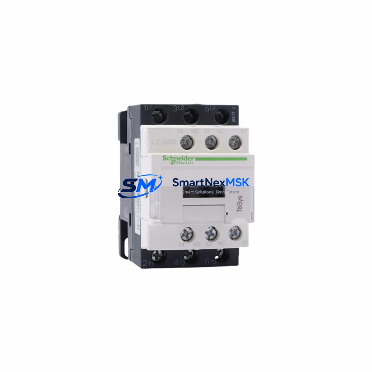
Schneider LC1D205M7C Retrofit-Ready AC Contactor for TeSys D Control Systems
The Schneider Electric LC1D205M7C is a 95A, 3-pole AC contactor from the TeSys D series, engineered for seamless integration into legacy motor control centers, control cabinets, and automation panels. With a 220VAC (M7) coil voltage and IEC 60947-4-1 compliance, this contactor is a verified drop-in replacement for discontinued or aging TeSys D units across a wide range of industrial retrofit and upgrade projects. Whether you are modernizing a 1990s-era motor starter panel or recovering a critical production line from a failed contactor, the LC1D205M7C delivers the electrical and mechanical compatibility required for a controlled, low-risk migration.
Upgrade Compatibility Table
| Parameter | LC1D205M7C Specification | Retrofit Notes |
|---|---|---|
| Rated Current (AC-3) | 95A @ 400V | Verify load current does not exceed 95A continuous |
| Coil Voltage | 220VAC / 50–60Hz (M7) | Confirm control circuit voltage before wiring; M7 = 220VAC |
| Pole Configuration | 3-pole (3NO main contacts) | Matches standard 3-phase motor starter wiring |
| Auxiliary Contact | 1NO + 1NC (integrated) | Verify PLC input wiring for auxiliary feedback signals |
| Mounting | DIN rail / screw mount | Compatible with standard 35mm DIN rail in existing cabinets |
| Overload Relay Compatibility | LRD series (LRD3359, LRD3361) | Clip-on mounting; verify thermal class and trip curve |
| Communication Compatibility | Modbus RTU via TeSys T / TeSys U gateway | Retain existing Modbus node address; update register map if needed |
| Replacement for | LC1D205, LC1D205B7C, LC1D205F7C, LC1D205Q7C | Coil voltage suffix differs; verify suffix before ordering |
| Installation Standard | IEC 60947-4-1 | Meets CE, RoHS; suitable for global industrial installations |
| Warranty | 12-Month Warranty | Covered from date of shipment; includes functional test report |
Retrofit Planning for Existing Automation Systems
Successful integration of the LC1D205M7C into an existing control system begins with a thorough audit of the original panel documentation. Before removing the failed or obsolete contactor, photograph all terminal wiring, record the existing coil voltage from the nameplate, and confirm the control circuit source — whether it originates from a Schneider Electric Zelio Logic SR3B261FU relay, a Modicon M340 PLC digital output module, or a dedicated motor protection relay such as the LRD3359 overload relay.
In panels where the LC1D205M7C replaces an older LC1D205B7C (24VAC coil) or LC1D205F7C (110VAC coil), the coil voltage suffix must be carefully matched. The M7 suffix designates a 220VAC coil; installing a mismatched coil voltage will result in either coil burnout or failure to energize. If the control transformer secondary voltage has been changed during a previous upgrade, verify the actual voltage at the coil terminals with a multimeter before energizing.
For systems using a TeSys U LUCA12BL or TeSys T LTMR08MBD motor management relay, the LC1D205M7C integrates directly into the existing control architecture. The auxiliary contact block — typically a LADN11 auxiliary contact block — can be transferred from the old contactor to the new unit without rewiring, preserving the PLC feedback signal wiring to the digital input module. If the panel uses a Modicon STB NIM 211 network interface module for distributed I/O, confirm that the auxiliary contact address mapping in the PLC program remains unchanged after the swap.
Where the retrofit involves upgrading from a non-TeSys platform — such as replacing a legacy Siemens 3RT1046 or ABB A95-30 contactor — terminal pitch and busbar spacing must be verified against the existing copper busbars and cable lug sizes. In most cases, a LAD9R2 reversing contactor kit or a custom terminal adapter plate will be required to maintain the original cable routing without re-terminating the main power cables. This is especially important in high-current applications where cable re-termination under load risk is unacceptable.
For systems with Profibus DP or CANopen communication backbones, the LC1D205M7C can be monitored via a TeSys T gateway LTMCU connected to the existing fieldbus segment. Confirm the gateway firmware version supports the contactor’s diagnostic register set, and update the GSD/EDS file in the PLC configuration tool if the gateway has been replaced during the retrofit. All I/O address assignments and symbolic variable names in the PLC program should be validated against the updated hardware configuration before the first test run.
Downtime Control During System Migration
Minimizing production downtime during a contactor replacement requires a structured pre-outage preparation protocol. Before the scheduled maintenance window, pre-stage the LC1D205M7C alongside all ancillary components — including the LRD3359 overload relay, LADN11 auxiliary contact block, and any required DIN rail mounting hardware — so that the physical swap can be completed within a single shift.
Prior to de-energizing the panel, export a full backup of the PLC program from the Modicon M340 or Modicon M580 controller using Unity Pro XL or EcoStruxure Control Expert. Store the backup on an isolated USB drive and verify the checksum. This ensures that if the PLC loses its program during a power interruption — a risk in older CPUs with degraded battery backup — the logic can be restored immediately without waiting for engineering support.
During the swap, label all control wiring with numbered ferrules before disconnecting. Use a wiring diagram cross-referenced against the original panel schematic to confirm terminal assignments for the coil (A1/A2), main power (1/L1, 3/L2, 5/L3, 2/T1, 4/T2, 6/T3), and auxiliary contacts (13/14 NO, 21/22 NC). After mechanical installation, perform a continuity check on all main and auxiliary circuits before re-energizing. Apply control voltage to the coil terminals and verify contactor pull-in and drop-out at the rated voltage range (85%–110% of 220VAC).
For critical processes where even a brief interruption is unacceptable, consider a hot-standby bypass strategy: install the LC1D205M7C in parallel with the existing contactor using a manual transfer switch, verify operation under load, then remove the old unit during the next planned maintenance window. This approach is particularly effective in water treatment, pharmaceutical, and continuous chemical process environments where stopping the motor even momentarily triggers a process alarm or safety interlock.
Retrofit Support FAQ
Q1: Is the LC1D205M7C a direct drop-in replacement for the LC1D205 (without suffix)?
The LC1D205 base model uses a 220VAC coil, which is identical to the M7 suffix. The LC1D205M7C is therefore a direct electrical and mechanical replacement for the LC1D205 in most applications. Always verify the coil voltage from the original nameplate before ordering, as other suffix variants (B7 = 24VAC, F7 = 110VAC, Q7 = 380VAC) are not interchangeable.
Q2: Can the LC1D205M7C be used with the existing LRD overload relay without modification?
Yes. The LC1D205M7C accepts clip-on LRD series overload relays, including the LRD3359 (80–104A) and LRD3361 (95–120A). Confirm the overload relay trip class and current setting range matches the motor FLA (full load amperage) before installation. No additional adapter or bracket is required for LRD series relays.
Q3: What commissioning checks are required after installation?
After mechanical installation and wiring, perform the following: (1) Insulation resistance test on main power terminals (≥1MΩ at 500VDC); (2) Coil pull-in/drop-out voltage test at 85% and 110% of rated coil voltage; (3) Auxiliary contact continuity check with the contactor energized and de-energized; (4) Overload relay trip test at 125% of set current using a primary injection test set; (5) PLC I/O verification — confirm auxiliary contact feedback signals are correctly received by the digital input module and reflected in the SCADA/HMI display.
Q4: What does the 12-month warranty cover, and what is included at shipment?
Every LC1D205M7C shipped by SMARTNEXMSK is covered by a 12-month warranty from the date of shipment. Each unit undergoes a pre-shipment functional test including coil energization, contact resistance measurement, and auxiliary contact verification. A test report is included with the shipment. The warranty covers manufacturing defects and functional failures under normal operating conditions. It does not cover damage resulting from incorrect installation, overvoltage, or mechanical impact. For warranty claims, contact [email protected] with the order number and a description of the fault.
© 2026 SMARTNEXMSK. All rights reserved.
Original Source: https://smartnexmsk.com
Contact: [email protected] | +86 18259474341