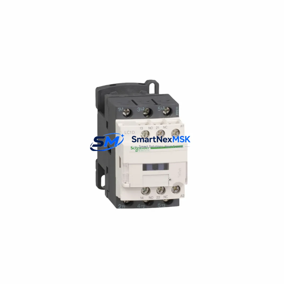
Schneider LC1D25M7C Retrofit-Ready AC Contactor for TeSys D Control Systems
The Schneider Electric LC1D25M7C is a 25A three-pole AC contactor from the TeSys D series, engineered for seamless integration into legacy motor control centers, control cabinets, and automation panels. As industrial facilities face increasing pressure to modernize aging infrastructure without full system overhauls, the LC1D25M7C has become a preferred retrofit solution for engineers replacing discontinued contactors, upgrading overloaded switching circuits, and restoring reliable motor control in production environments where downtime is not an option.
Whether you are migrating from an older TeSys F or TeSys B series installation, replacing a failed LC1D18 or LC1D32 unit in a running line, or expanding an existing motor starter assembly with a new LC1D25M7C alongside an LRD thermal overload relay, this contactor delivers the dimensional and electrical compatibility that retrofit projects demand. Its 220V AC coil (M7 designation) aligns with the most common control voltage found in European and Asian industrial panels, and its 45mm DIN rail footprint matches standard TeSys D mounting arrangements without requiring panel rework.
Upgrade Compatibility Table
| Parameter | LC1D25M7C Specification | Retrofit Notes |
|---|---|---|
| Rated Current (AC-3) | 25A @ 400V | Direct replacement for LC1D18 (uprate) or LC1D32 (downrate with load review) |
| Coil Voltage | 220V AC / 50–60Hz (M7) | Verify existing control transformer output before wiring |
| Pole Configuration | 3-Pole + 1NO Auxiliary | Auxiliary contact compatible with standard TeSys D add-on blocks |
| Mounting | 35mm DIN Rail / Screw | No panel modification required for TeSys D rail installations |
| Communication Compatibility | Compatible with TeSys T motor management relay via hardwired I/O | Confirm I/O address mapping in PLC program before commissioning |
| Add-on Blocks | Accepts LAD4RCU suppressor, LADN auxiliary contact blocks | Reuse existing add-on blocks from replaced unit where condition permits |
| Replacement Path | LC1D18M7C → LC1D25M7C → LC1D32M7C | Upward migration requires load current verification |
| Warranty | 12 Months | Covers manufacturing defects; includes pre-shipment functional test |
Retrofit Planning for Existing Automation Systems
Successful integration of the LC1D25M7C into an existing control system begins well before the unit arrives on site. Engineers should start by auditing the control cabinet layout to confirm available DIN rail space, terminal block clearance, and cable routing paths. In many legacy installations, the original LC1D18M7C or LC1D25 unit was mounted alongside a GV2ME manual motor starter or a LRD14 thermal overload relay — both of which can typically be retained during a contactor-only swap, reducing material cost and reconfiguration time.
Power supply capacity is a critical checkpoint. The LC1D25M7C coil draws approximately 70VA at energization and 7VA at hold. If the existing 24VDC or 220VAC control power supply — such as a Phaseo ABL8 series unit — is already near capacity due to added I/O modules or HMI panels, a load calculation must be completed before commissioning. Overloaded control supplies are a common root cause of intermittent contactor dropout in retrofit projects.
Terminal wiring should be verified against the original panel drawings. The LC1D25M7C uses the same L1/L2/L3 and T1/T2/T3 power terminal layout as other TeSys D contactors, but wire ferrule sizing and torque specifications (typically 2.5 Nm for power terminals) must be confirmed. Where the original installation used a CAD32 auxiliary contact block or a LADN11 add-on block for interlock circuits feeding a Modicon M340 or Modicon M580 PLC digital input card, these blocks can be transferred directly to the replacement unit.
For systems using Profibus DP or Modbus RTU communication between a TeSys T motor management relay and the PLC rack, no protocol reconfiguration is required when replacing the contactor itself — the TeSys T relay remains in circuit and continues to report motor current, thermal state, and fault status to the controller. However, if the retrofit involves replacing the TeSys T relay as well, the device address, baud rate, and parity settings must be re-entered and verified against the PLC communication module configuration, whether that module is a BMX NOE 0100 Ethernet module or a legacy TSX SCY 21601 serial card.
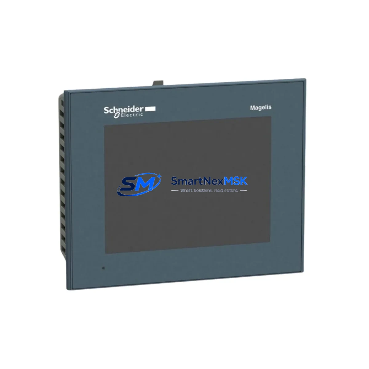
Where the control system includes an HMI panel — such as a Magelis HMIGTO or a Vijeo Designer-configured touch panel — screen objects linked to contactor status bits should be tested in simulation mode before live commissioning to confirm that feedback signals from the auxiliary contact are correctly mapped to the display logic. This step is frequently overlooked in fast-turnaround retrofit jobs and can result in misleading operator displays after restart.
Downtime Control During System Migration
Minimizing production downtime during a contactor replacement requires a structured pre-work sequence. Before de-energizing the panel, capture a full backup of the PLC program from the connected Modicon M340, M580, or Premium controller using Unity Pro or EcoStruxure Control Expert software. Even if no program changes are planned, having a verified backup eliminates recovery risk if a power interruption during the swap corrupts the controller memory.
Isolate the motor circuit at the upstream circuit breaker or GV3 manual motor starter, and lock out / tag out (LOTO) the panel before removing the failed contactor. Label all control wiring — particularly the coil terminals A1/A2 and any auxiliary contact wiring — before disconnection. Photograph the original wiring arrangement as a reference. The LC1D25M7C can typically be installed and re-wired within 20–40 minutes by a qualified electrician familiar with TeSys D hardware, keeping total panel downtime well under one hour in most scenarios.
After installation, perform a continuity check on all power and control terminals before re-energizing. Apply control voltage to the coil and verify that the contactor closes cleanly and that the auxiliary contact feedback reaches the PLC input card. Run the motor in jog mode first to confirm rotation direction and confirm that the LRD thermal overload relay trip threshold is correctly set for the connected motor’s full-load current. Only after these checks should the system be returned to automatic control mode.
Each LC1D25M7C unit shipped by SMARTNEXMSK undergoes a pre-shipment functional test covering coil energization, contact resistance measurement, and mechanical operation verification, supporting a smooth and confident installation on arrival.
Retrofit Support FAQ
Q: Is the LC1D25M7C a direct drop-in replacement for the LC1D18M7C?
A: Dimensionally and electrically, yes — both share the same TeSys D footprint, coil voltage, and terminal layout. However, the LC1D25M7C is rated for 25A versus 18A, so you should verify that the connected motor load does not exceed the original design intent. The LRD thermal overload relay setting should be adjusted to match the actual motor full-load current.
Q: Can I reuse the existing LADN auxiliary contact block from the old contactor?
A: In most cases, yes. TeSys D series add-on blocks including LADN11, LADN20, and CAD32 auxiliary contact blocks are mechanically compatible across the TeSys D range. Inspect the block for wear or contact damage before reuse, and replace if contact resistance exceeds acceptable limits.
Q: What communication protocols are supported when integrating with a Modicon PLC?
A: The LC1D25M7C itself is a hardwired device with no onboard communication. Integration with Modicon M340 or M580 controllers is achieved through the auxiliary contact outputs wired to digital input cards, or through a TeSys T motor management relay connected via Modbus RTU or Profibus DP. No firmware or protocol configuration is required on the contactor itself.
Q: What does the 12-month warranty cover, and is pre-shipment testing included?
A: The 12-month warranty covers manufacturing defects in materials and workmanship from the date of shipment. Every unit undergoes a pre-shipment functional test including coil energization and contact operation verification before dispatch. In the event of a warranty claim, SMARTNEXMSK provides replacement or repair support with documented test records available on request.
© 2026 SMARTNEXMSK. All rights reserved.
Original Source: https://smartnexmsk.com
Contact: [email protected] | +86 18259474341