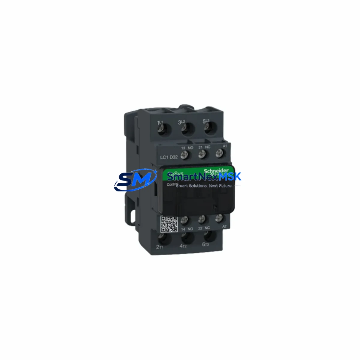
Schneider LC1D32M7C Maintenance-Ready Spare TeSys D Automation
The Schneider Electric LC1D32M7C is a 32A three-pole AC contactor from the TeSys D series, one of the most widely deployed contactor families in industrial automation worldwide. Designed for motor control, load switching, and power distribution applications, this contactor is a critical component in motor control centers (MCCs), control cabinets, and distributed automation panels across manufacturing, utilities, water treatment, and process industries. When an LC1D32M7C fails or reaches end-of-life, rapid replacement with a verified original spare is essential to minimize unplanned downtime and restore production continuity.
At SMARTNEXMSK, every LC1D32M7C unit is sourced from authorized supply channels, inspected prior to dispatch, and shipped with full traceability documentation. Our 12-month warranty covers all original spare parts, giving maintenance engineers and procurement teams confidence in both quality and long-term supply availability.
Spare Maintenance Table
| Parameter | Specification |
|---|---|
| SKU / Part Number | LC1D32M7C |
| Brand | Schneider Electric |
| Series | TeSys D |
| Product Type | AC Contactor (3-Pole) |
| Rated Current (Ie) | 32A @ AC-3 |
| Coil Voltage | 220VAC / 50–60Hz |
| Poles | 3 Main Poles + 1 NO Auxiliary |
| Motor Rating (AC-3, 400V) | 15 kW |
| Mounting | DIN Rail / Screw Mount |
| Enclosure / IP Rating | Open Type (IP20 terminals) |
| Operating Temperature | -5°C to +60°C |
| Compatibility | TeSys D series; replaces LC1D32M7, LC1D32M7TQ, LC1D32M7CC |
| Origin | France |
| Warranty | 12 Months from date of shipment |
| Condition | Original New, Factory Sealed |
| Shipping | Tested before dispatch; global express available |
Maintenance Planning for Continuous Operation
Replacing an LC1D32M7C in the field is rarely an isolated task. Experienced maintenance engineers know that a contactor failure is often a symptom of broader stress in the electrical circuit. Before returning the panel to service, a thorough inspection of the surrounding components is strongly recommended.
Start with the overload relay — the LC1D32M7C is typically paired with a TeSys D LRD series thermal overload relay (such as the LRD32 or LRD3353 for 32A applications). If the contactor has failed due to overload or short-circuit conditions, the overload relay trip mechanism and bimetal elements should be tested and reset, or replaced if signs of thermal damage are present.
Next, inspect the control circuit fusing and wiring. The 220VAC coil circuit should be protected by a dedicated control fuse (typically 2A–4A), and the coil wiring insulation should be checked for heat damage or brittleness. Loose or corroded terminals on the coil connections (A1/A2) are a common cause of intermittent contactor chatter and premature coil burnout.
For panels using auxiliary contact blocks — such as the LADN11 or LADN22 add-on blocks — verify that the auxiliary contacts are making clean, low-resistance contact. These auxiliary contacts feed PLC digital inputs (DI) for motor run feedback and fault status signals. A worn auxiliary contact can cause false fault indications or prevent the PLC from confirming motor start, leading to nuisance trips in the control logic.
If the LC1D32M7C is part of a star-delta starter or reversing starter assembly, the companion contactors (typically LC1D09 to LC1D18 range for the star contactor) and the associated mechanical interlock kit (LAD9R2) should also be inspected for wear and proper operation. Mechanical interlocks are safety-critical and must be confirmed functional before re-energizing the circuit.
In panels with Schneider Electric Zelio Logic smart relays or Modicon M221/M241 PLCs controlling the motor circuit, verify that the PLC output module driving the contactor coil is within its rated output current. Repeated coil switching at high frequency can stress solid-state output modules; if the output card shows signs of overheating or erratic behavior, it should be replaced alongside the contactor.
For installations using power factor correction capacitors or soft starters (such as the Altistart ATS22 or ATS48 series) in the same distribution board, confirm that the capacitor bank contactors and soft starter bypass contactors are also in good condition. Capacitor switching generates high inrush currents that accelerate contact wear across all contactors in the panel.
Finally, check the terminal blocks and busbar connections (Schneider Linergy or equivalent) for signs of overheating, discoloration, or loose torque. Thermal imaging of the panel under load, if available, is the most efficient way to identify hot spots before they cause a secondary failure.
Site Replacement Workflow
Step 1 — Isolation and Lockout/Tagout (LOTO): De-energize the motor circuit and apply LOTO procedures per site safety standards. Confirm zero voltage on all three main poles using a calibrated voltage tester before proceeding.
Step 2 — Document existing wiring: Photograph or sketch the main power connections (L1/L2/L3 → T1/T2/T3), coil connections (A1/A2), and any auxiliary contact wiring before disconnecting. This is especially important in older installations where wiring may deviate from standard drawings.
Step 3 — Remove the failed unit: Disconnect main power cables, coil wiring, and auxiliary contact wiring. If an overload relay (LRD series) is clipped onto the bottom of the contactor, it can typically be unclipped and retained if it is in good condition, avoiding the need to re-wire the overload relay terminals.
Step 4 — Install the LC1D32M7C replacement: Mount the new contactor on the DIN rail or screw-mount position. Re-attach the overload relay if retained. Reconnect all wiring per the documented layout, ensuring correct torque on all terminals (refer to Schneider Electric installation datasheet for torque values).
Step 5 — Functional verification: Before re-energizing the motor, perform a coil continuity check and insulation resistance test on the main contacts. After energizing, confirm correct operation via the PLC HMI or local control panel — verify motor run feedback, overload relay status, and auxiliary contact signals are all correct.
Step 6 — Update maintenance records: Log the replacement date, new unit serial number, and any observations about the failure mode. This data supports predictive maintenance planning and helps identify recurring failure patterns in specific panels or circuits.
Spare Parts Support FAQ
Q1: Is the LC1D32M7C compatible with older TeSys D contactors already installed in my panel?
Yes. The LC1D32M7C is a direct form-fit-function replacement for earlier TeSys D 32A contactors with 220VAC coils, including the LC1D32M7 and LC1D32M7TQ. Mounting dimensions, terminal positions, and auxiliary contact block interfaces are identical, allowing drop-in replacement without panel modification.
Q2: How do you verify the unit before shipment?
Each LC1D32M7C unit undergoes a pre-shipment inspection covering coil resistance measurement, main contact continuity check, and mechanical operation verification. Units are shipped in original or equivalent protective packaging with a test record. Our 12-month warranty covers any defects in materials or workmanship from the date of shipment.
Q3: Can you support long-term or blanket purchase orders for ongoing maintenance programs?
Yes. SMARTNEXMSK supports scheduled delivery agreements and blanket PO arrangements for maintenance teams that require guaranteed stock availability. Contact our sales team to discuss lead times, pricing tiers, and consignment stock options for high-usage spare parts.
Q4: What if my system uses a different coil voltage — can I get the LC1D32 in other coil variants?
The LC1D32 frame is available in multiple coil voltage variants: 24VAC (B7C), 110VAC (F7C), 230VAC (P7C), 24VDC (BD), and 48VDC (ED), among others. If your installation requires a different coil voltage, contact us with your full part number and we will confirm availability and lead time.
© 2026 SMARTNEXMSK. All rights reserved.
Original Source: https://smartnexmsk.com
Contact: [email protected] | +86 18259474341