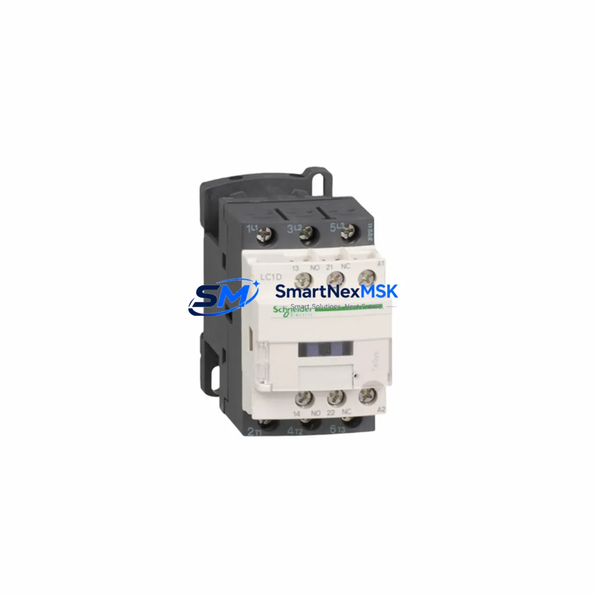
Schneider LC1D40M7C Retrofit-Ready Contactor for TeSys D Control Systems
The Schneider Electric LC1D40M7C is a 40A, 3-pole AC contactor from the TeSys D series, engineered for seamless integration into legacy motor control centers, control cabinets, and automation panels. Whether you are replacing a failed unit on an aging production line, upgrading a discontinued contactor in a retrofit project, or expanding I/O capacity in an existing control system, the LC1D40M7C delivers the electrical and mechanical compatibility required for a smooth, low-risk transition.
Rated at 18.5 kW / 400 V (AC-3 duty), the LC1D40M7C accepts a 220 V AC coil (suffix M7), making it directly interchangeable with earlier TeSys D variants such as the LC1D40 and LC1D40A, as well as compatible with panel layouts originally designed around the legacy TeSys F series. Its standardized 45 mm DIN rail footprint and front-wired terminal block arrangement mean that existing cable looms, ferrule-terminated conductors, and busbar connections can typically be reused without modification — a critical advantage when downtime windows are measured in hours, not days.
In retrofit scenarios involving older Schneider Modicon TSX Micro or Modicon M340 PLC platforms, the LC1D40M7C is commonly deployed alongside the LC1D09M7C and LC1D18M7C contactors to form a coordinated motor starter group within the same control cabinet. When the application requires reversing duty, engineers pair the LC1D40M7C with a LAD4RCU mechanical interlock kit, eliminating the need for additional panel space or custom fabrication. For applications where the original design used a TeSys GV2ME motor circuit breaker upstream, the LC1D40M7C maintains full coordination class 2 compatibility, preserving the original protection philosophy without requiring a full panel redesign.
Communication protocol migration is another common driver for LC1D40M7C deployments. As facilities transition from hardwired relay logic to networked architectures using CANopen, Modbus RTU, or EtherNet/IP, the contactor’s coil interface remains compatible with both direct PLC digital output modules — such as the TM3DQ16R discrete output expansion module — and smart relay controllers like the Zelio Logic SR3B261FU. This flexibility allows the contactor to serve as a stable actuator layer while the supervisory control architecture is progressively modernized.
For panel builders and system integrators managing multi-cabinet upgrades, the LC1D40M7C is frequently specified alongside LRD22 overload relays (16–24 A range) or LRD32 overload relays (23–32 A range) to form a complete IEC-compliant motor starter assembly. The overload relay clips directly onto the contactor base without tools, preserving the compact footprint of the original TeSys D design. Where the legacy installation used a separate auxiliary contact block, the LADN22 add-on auxiliary contact module provides 2NO + 2NC contacts and mounts to the front face of the LC1D40M7C without requiring panel cutout modifications.
Before completing the physical swap, field engineers should verify the following during the retrofit planning phase: confirm that the existing power supply rail can sustain the 220 V AC coil inrush current (typically 70 VA pick-up, 7 VA holding); inspect terminal torque specifications (main terminals: 4–6 N·m; auxiliary terminals: 1.2–1.5 N·m); validate that the backplane or DIN rail section is rated for the combined weight of the contactor and any add-on modules; and confirm that the PLC output module driving the coil circuit is rated for inductive load switching. If the original program logic uses a latching coil instruction (SET/RESET in IEC 61131-3 ladder), no program modification is required — the LC1D40M7C responds identically to its predecessors on the same coil voltage.
HMI screen updates are typically minimal when replacing like-for-like within the TeSys D family. Status feedback signals — contactor energized, overload tripped, auxiliary contact state — map directly to the same PLC input addresses used by the original unit, provided the LADN auxiliary block wiring is preserved. Where the original installation used a Magelis HMIGTO2310 or similar Schneider HMI panel, no tag remapping is required for standard motor run/stop/fault indication screens.
All LC1D40M7C units supplied by SMARTNEXMSK are sourced from authorized distribution channels, individually inspected prior to dispatch, and covered by a 12-month warranty against manufacturing defects. Each unit ships with original manufacturer packaging, a traceable batch label, and a pre-shipment test record. Stock is maintained in Xiamen for rapid fulfillment to domestic and international customers, with typical lead times of 1–3 business days for in-stock orders.
Upgrade Compatibility Table
| Parameter | LC1D40M7C (This Unit) | Typical Legacy / Replaced Unit | Retrofit Notes |
|---|---|---|---|
| Rated Current (AC-3) | 40 A | 40 A (LC1D40, LC1D40A) | Direct current rating match; no derating required |
| Coil Voltage | 220 V AC / 50–60 Hz (M7) | 220 V AC (M7) or 230 V AC (P7) | Verify coil suffix on original unit; M7 and P7 are interchangeable in most 220–230 V systems |
| Pole Configuration | 3-pole (3NO main) | 3-pole | No change; standard motor starter configuration |
| Mounting | 35 mm DIN rail or screw mount | 35 mm DIN rail | Compatible with existing rail; check rail section length for add-on modules |
| Main Terminal Type | Screw clamp, 1–35 mm² | Screw clamp, 1–35 mm² | Existing cable ferrules and lugs reusable; re-torque to 4–6 N·m |
| Auxiliary Contact Add-on | LADN series (front mount) | LADN series | Existing LADN block transfers directly; no rewiring needed |
| Overload Relay Compatibility | LRD series (clip-on) | LRD series | LRD22 / LRD32 clip directly; verify trip class setting after installation |
| Communication Interface | Coil-driven (hardwired DO) | Coil-driven (hardwired DO) | Compatible with TM3DQ16R and equivalent PLC output modules |
| Warranty | 12 Months — Manufacturing Defects, Parts & Labor | ||
Retrofit Planning for Existing Automation Systems
A successful LC1D40M7C retrofit begins with a thorough audit of the existing control cabinet. Start by documenting the original wiring diagram and confirming the coil control circuit: identify whether the PLC digital output driving the contactor coil is a relay output (suitable for inductive loads) or a transistor output (which may require a snubber circuit for AC coil applications). In multi-motor panels where several TeSys D contactors — such as the LC1D09M7C, LC1D12M7C, and LC1D25M7C — share a common 24 V DC or 220 V AC control bus, verify that the total coil inrush demand does not exceed the control transformer or SMPS capacity during simultaneous energization events.
For systems incorporating a Schneider Altivar ATV312 or ATV630 variable frequency drive upstream of the contactor, confirm that the contactor is positioned on the line side (input) rather than the motor side (output) of the drive. Switching a contactor on the output of a VFD while the drive is running can cause overcurrent faults or damage to the drive’s IGBT output stage — a critical point that must be addressed in the retrofit procedure and communicated to the commissioning team.
Where the original panel used a Schneider XPSAF5130 safety relay or equivalent safety module to control the contactor coil in a safety-rated stop circuit (SIL 2 / PLd), the LC1D40M7C must be validated as part of the safety function re-verification process. This typically involves confirming the contactor’s B10d value, calculating the PFHd for the updated safety function, and documenting the validation in the machine’s technical file. SMARTNEXMSK can provide the relevant product safety data sheets upon request to support this process.
Backplane and rack considerations apply when the LC1D40M7C is installed in a motor control center (MCC) drawer or a withdrawable unit. Confirm that the drawer’s stab connector rating matches the contactor’s terminal configuration, and that the drawer’s mechanical interlock mechanism is compatible with the LC1D40M7C’s body dimensions. In most Schneider Okken and Prisma MCC configurations, the TeSys D 40A frame is a standard drawer size, and no mechanical adaptation is required.
Downtime Control During System Migration
Minimizing production downtime during a contactor replacement requires a structured hot-swap procedure. Before de-energizing the panel, photograph the existing wiring layout and label every conductor at both ends using the original drawing reference. For three-phase motor circuits, use a phase rotation meter to confirm L1/L2/L3 sequence before disconnection — this prevents motor reversal on restart, which is a common and costly commissioning error in retrofit projects.
Where the process cannot tolerate a full shutdown, consider a staged replacement approach: install the LC1D40M7C in a parallel position on the DIN rail, pre-wire all control and power conductors to the new unit, and perform a live transfer during a scheduled micro-outage (typically 30–60 seconds). This approach is particularly effective in continuous process industries — food and beverage, water treatment, chemical — where even brief interruptions trigger batch rejection or process upset conditions.
After physical installation, perform the following commissioning checks before restoring power: verify insulation resistance between phases and phase-to-earth (minimum 1 MΩ at 500 V DC); confirm coil circuit continuity; check that all auxiliary contact wiring matches the original drawing; and verify that the overload relay trip current is set to match the motor nameplate full-load amperage. Once power is restored, perform a no-load energization test — observe the contactor for abnormal noise, coil chatter, or contact bounce — before applying the full motor load. Document the commissioning results and retain them with the panel’s maintenance record.
The LC1D40M7C’s identical footprint and terminal layout to its TeSys D predecessors means that program logic changes are rarely required. The PLC retains its original output address assignments, the HMI retains its original tag bindings, and the SCADA system continues to receive status feedback without modification. This program-transparent replacement approach is the primary reason TeSys D remains the preferred contactor family for retrofit engineers managing legacy Schneider automation platforms.
Retrofit Support FAQ
Q1: Is the LC1D40M7C a direct drop-in replacement for the LC1D40A or LC1D40BD?
The LC1D40M7C (220 V AC coil) is a direct mechanical replacement for the LC1D40A (220 V AC coil, older catalog suffix). If the original unit is an LC1D40BD (24 V DC coil), the coil voltage is different and the LC1D40M7C cannot be substituted without modifying the control circuit. In that case, the correct replacement is the LC1D40BD or its current equivalent. Always verify the coil voltage suffix before ordering.
Q2: What pre-shipment testing is performed on each LC1D40M7C unit?
Each unit undergoes a visual inspection for physical damage, a coil continuity and resistance check, a main contact resistance measurement (typically <1 mΩ per pole), and an operational test confirming correct pick-up and drop-out at rated coil voltage. A test record is included with each shipment. Units that do not pass all checks are quarantined and not dispatched.
Q3: Can the LC1D40M7C be used with the existing LRD overload relay from the replaced unit?
Yes, provided the LRD relay is in the correct current range for the application (e.g., LRD22 for 16–24 A, LRD32 for 23–32 A) and is in serviceable condition. The LRD series clips directly onto the LC1D40M7C base without tools. However, if the original overload relay shows signs of thermal damage, contact erosion, or has tripped repeatedly due to overload conditions, it is strongly recommended to replace it simultaneously with the contactor to avoid nuisance tripping or undetected fault conditions after restart.
Q4: What does the 12-month warranty cover, and how is a warranty claim processed?
The 12-month warranty covers manufacturing defects in materials and workmanship from the date of shipment. It does not cover damage resulting from incorrect installation, overvoltage, short-circuit events beyond the contactor’s rated breaking capacity, or unauthorized modification. To initiate a warranty claim, contact SMARTNEXMSK at [email protected] with the order reference, batch label photograph, and a description of the fault. Replacement units are dispatched within 3 business days of claim approval, and defective units must be returned for failure analysis within 30 days.
© 2026 SMARTNEXMSK. All rights reserved.
Original Source: https://smartnexmsk.com
Contact: [email protected] | +86 18259474341