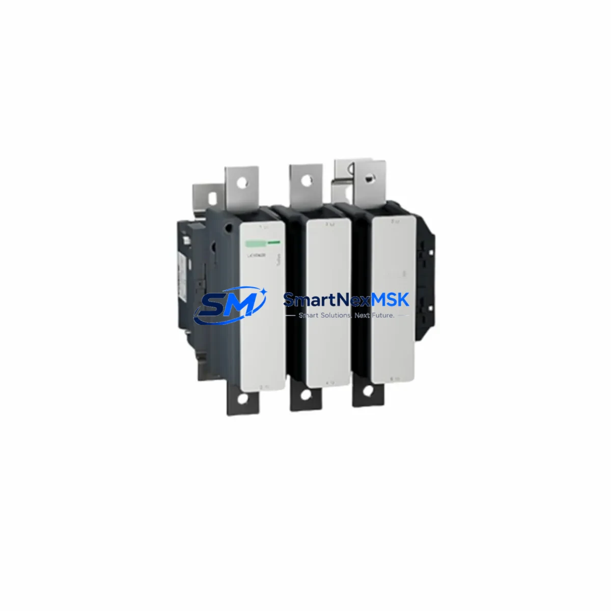
Schneider LC1D620M7C Retrofit-Ready Contactor for TeSys D Control Systems
The Schneider Electric LC1D620M7C is a 620A, 3-pole AC contactor from the TeSys D series, engineered for high-current motor control and power switching in industrial automation environments. As legacy control panels age and original equipment reaches end-of-life, the LC1D620M7C serves as a verified retrofit-ready replacement for discontinued or hard-to-source contactors in the same power class. Whether you are modernizing a motor control center (MCC), upgrading a control cabinet, or restoring a production line after an unplanned failure, this contactor delivers the electrical and mechanical compatibility required for a smooth, low-risk transition.
Rated at AC-3 duty for squirrel-cage motor applications, the LC1D620M7C operates with a 220VAC (50/60Hz) coil — designated by the M7 coil suffix — and is designed for direct mounting on standard DIN rail or panel backplates. Its 3-pole main contact configuration aligns with the majority of three-phase motor starters found in legacy automation systems, making it a practical drop-in solution for plants running older Schneider TeSys B, TeSys F, or early TeSys D generation hardware.
Upgrade Compatibility Table
| Parameter | LC1D620M7C Specification | Retrofit Notes |
|---|---|---|
| Rated Current (AC-3) | 620A | Verify upstream fuse and cable sizing match 620A rating |
| Poles | 3-pole | Direct replacement for 3-pole legacy contactors in same frame |
| Coil Voltage | 220VAC, 50/60Hz (M7) | Confirm control circuit voltage before installation; M5=110VAC, M7=220VAC |
| Mounting | DIN rail / panel mount | Compatible with standard 35mm DIN rail; check backplate clearance |
| Auxiliary Contact | 1NO+1NC (standard) | Add LA1DN11 or LA1DK11 auxiliary contact block if additional interlocks required |
| Communication Compatibility | Standalone; integrates with TeSys T motor management relay | Pair with LTM R motor management relay for Modbus RTU or EtherNet/IP monitoring |
| Replacement Candidates | LC1D620, LC1F630, LC1D580 | Verify terminal pitch and busbar connection before substitution |
| Commissioning Focus | Coil wiring, auxiliary wiring, torque specs | Follow Schneider tightening torque table; re-test interlock logic after swap |
| Warranty | 12 Months | Covered from date of shipment; includes functional and coil failure |
Retrofit Planning for Existing Automation Systems
Successful integration of the LC1D620M7C into an existing control system requires a structured pre-installation review. Begin by auditing the control cabinet layout: confirm that the existing busbar arrangement, terminal block spacing, and backplate dimensions are compatible with the LC1D620M7C’s physical footprint. In many legacy MCC installations, the contactor is mounted alongside a Schneider GV7 or GV3 motor circuit breaker for upstream short-circuit protection — verify that the breaker’s rated current and breaking capacity remain appropriate for the upgraded contactor.
For systems using a TeSys T LTM R motor management relay or an older LR9 thermal overload relay, check whether the relay’s current setting range covers the full-load ampere (FLA) of the connected motor. If the existing overload relay is undersized or incompatible, replacement with a matched LR9F7375 or LR2K0322 overload relay should be planned as part of the same retrofit scope. Skipping this step is a common cause of nuisance tripping after contactor replacement.
On the control wiring side, the LC1D620M7C’s A1/A2 coil terminals accept standard 1.5–4mm² control cable. If the existing panel uses a Schneider XMLA pressure switch, XB4 pushbutton station, or Harmony XB5 selector switch for start/stop control, these devices connect directly to the coil circuit without modification. Confirm that the control transformer or 24VDC power supply — often a Phaseo ABL8 series SMPS — has sufficient VA capacity to energize the LC1D620M7C coil under inrush conditions, which can be 6–10× the sealed coil current at the moment of energization.
Where the legacy system includes a Modicon M340 or M580 PLC controlling the contactor via a discrete output module, verify that the output module’s current rating and contact type (relay vs. transistor) are compatible with the coil load. For transistor outputs driving an interposing relay, ensure the relay coil voltage matches the PLC output supply. If the system uses a Schneider Altivar ATV312 or ATV630 variable frequency drive with a bypass contactor circuit, the LC1D620M7C must be interlocked with the drive’s run permissive signal to prevent simultaneous energization of the bypass and drive output contactors.
Finally, if the plant’s SCADA or DCS system monitors contactor status via auxiliary contacts wired to a Modicon STB or Advantys island bus I/O module, confirm that the auxiliary contact block fitted to the LC1D620M7C provides the correct number of NO/NC contacts for the existing I/O map. Adding a LA1DN22 auxiliary contact block can expand the contact count without requiring panel rewiring.
Downtime Control During System Migration
Minimizing production downtime during a contactor retrofit requires advance preparation and a disciplined changeover sequence. Before the scheduled maintenance window, pre-wire and bench-test the LC1D620M7C with its auxiliary contact block and coil wiring harness. Label all existing wires in the panel using the original schematic reference designators — this is critical for restoring the control circuit accurately if the PLC program uses hardwired interlock logic that cannot be easily re-verified from the HMI screen alone.
During the changeover, photograph the existing terminal connections before disconnecting any wires. Isolate the motor circuit using the upstream GV7 motor circuit breaker and lock out the control circuit at the control transformer secondary. Remove the old contactor, transfer the busbar connections and control wiring to the LC1D620M7C, and torque all terminals to the manufacturer’s specification. Re-energize the control circuit first and verify coil pickup and dropout before re-energizing the main power circuit.
After installation, perform a no-load test by jogging the motor in manual mode from the local control station. Confirm that the PLC’s I/O status display shows correct auxiliary contact feedback — typically a “contactor closed” bit in the Modicon M340 or M580 program. If the system uses a Vijeo Citect or Wonderware InTouch SCADA HMI, verify that the motor status graphic updates correctly before returning the system to automatic mode. Document the as-installed configuration, update the panel schematic, and retain the original contactor for failure analysis if required.
All units are pre-tested prior to shipment and covered by a 12-month warranty from the date of delivery. In-stock units typically ship within 1–3 business days, supporting urgent breakdown recovery scenarios where extended lead times from OEM channels are not acceptable.
Retrofit Support FAQ
Q1: Is the LC1D620M7C a direct drop-in replacement for the LC1D620 or LC1F630?
The LC1D620M7C shares the same 3-pole, 620A AC-3 rating as the LC1D620 base model. The M7C suffix denotes a 220VAC coil and Chinese market certification. Physical dimensions and terminal pitch are compatible with the LC1D620 frame. The LC1F630 is a higher-frame contactor — while electrically similar, the mounting footprint and busbar connection geometry differ, so a direct mechanical swap requires verification against the panel layout drawing before proceeding.
Q2: What commissioning checks are required after installation?
After fitting the LC1D620M7C, verify coil pickup voltage at the A1/A2 terminals under loaded control circuit conditions (not open-circuit). Check main contact resistance using a low-resistance ohmmeter across each pole. Confirm auxiliary contact continuity and correct NO/NC state with the contactor de-energized. Perform a full-load motor start and monitor for abnormal heating at the terminal connections after the first 30 minutes of operation.
Q3: Can the LC1D620M7C be used with a variable frequency drive bypass circuit?
Yes, provided the bypass interlock logic prevents simultaneous energization of the drive output contactor and the bypass contactor. The LC1D620M7C’s switching speed and contact bounce characteristics are compatible with standard bypass schemes used with Altivar ATV630 and ATV930 drives. Confirm that the drive’s output contactor and the bypass contactor are electrically and mechanically interlocked per the drive manufacturer’s wiring diagram.
Q4: What does the 12-month warranty cover?
The 12-month warranty covers manufacturing defects, coil failure under normal operating conditions, and main contact welding attributable to production faults. It does not cover damage resulting from installation errors, overvoltage events, incorrect coil voltage selection, or operation outside the rated AC-3 duty cycle. Warranty claims are processed from the date of shipment and require return of the defective unit for inspection.
© 2026 SMARTNEXMSK. All rights reserved.
Original Source: https://smartnexmsk.com
Contact: [email protected] | +86 18259474341