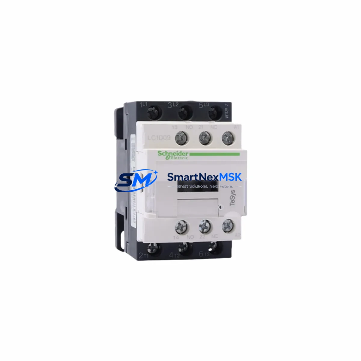
Schneider LC1D65M7C Retrofit-Ready Contactor for TeSys D Control Systems
The Schneider Electric LC1D65M7C is a 65A three-pole AC contactor from the TeSys D series, engineered for seamless integration into legacy motor control centers, control cabinets, and automation panels. As industrial facilities face increasing pressure to modernize aging infrastructure without full system overhauls, the LC1D65M7C has become a preferred retrofit solution for engineers replacing discontinued contactors, upgrading undersized switching components, and restoring reliable motor control in critical production lines.
With a 220V AC (M7) coil voltage, IEC-rated 65A thermal current, and AC-3 duty cycle rating, this contactor is a direct functional replacement for earlier TeSys D variants including the LC1D50, LC1D65, and LC1D80 in derated applications. Its standardized 45mm DIN rail footprint and front-face auxiliary contact block interface ensure backward compatibility with existing panel layouts, minimizing rewiring scope during retrofit projects.
Upgrade Compatibility Table
| Parameter | LC1D65M7C Specification | Retrofit Notes |
|---|---|---|
| Rated Current (AC-3) | 65A @ 400V | Verify motor FLA; derate for AC-4 duty |
| Coil Voltage | 220V AC / 50–60Hz (M7) | Confirm control transformer output before wiring |
| Pole Configuration | 3P (NO main contacts) | Add LA1DN11 auxiliary block for 1NO+1NC if required |
| Mounting | 35mm DIN rail or screw mount | Compatible with existing TeSys D rail positions |
| Auxiliary Contact Interface | Front-face clip-on (LA1D series) | Existing LA1DN10 / LA1DN01 blocks reusable |
| Communication Compatibility | Standalone; compatible with TeSys T overload relay | Pair with LRD332 or LRD340 for motor protection |
| Common Replacements | LC1D50M7C, LC1D65A, CJX2-65 (3rd party) | Verify coil voltage and terminal pitch before swap |
| Commissioning Focus | Coil inrush, contact bounce, overload relay reset | Test under no-load before full motor energization |
| Warranty | 12 Months | Covers coil failure, contact weld, mechanical defect |
Retrofit Planning for Existing Automation Systems
A successful LC1D65M7C retrofit begins well before the contactor arrives on-site. Engineers should first audit the existing control cabinet to confirm the available control voltage — many older panels supply 110V AC or 24V DC to the coil circuit, which would require a coil voltage variant other than the M7. Once coil compatibility is confirmed, attention shifts to the main power terminals: the LC1D65M7C uses standard screw-clamp terminals accepting up to 35mm² cable, compatible with most existing lug configurations in 65A motor feeders.
For systems where the original contactor was paired with a Schneider LRD332 or LRD340 TeSys D overload relay, the mechanical coupling interface is preserved — the overload relay clips directly onto the base of the LC1D65M7C without additional adapters. If the existing installation used a separate overload relay mounted on a DIN rail, verify that the relay’s trip class and current range match the motor’s full-load amperage before reuse.
In multi-motor control panels, the LC1D65M7C is frequently installed alongside smaller contactors such as the LC1D09M7C or LC1D18M7C for auxiliary motor circuits, star-delta starters, or reversing duty applications. When upgrading a star-delta starter, both the main contactor (LC1D65M7C) and the star contactor (typically an LC1D40M7C) should be replaced simultaneously to ensure uniform contact wear characteristics and consistent switching timing.
Control wiring to the coil terminals (A1/A2) should be inspected for insulation condition and terminal torque. The LC1D65M7C coil draws approximately 70VA at inrush and 7VA sealed — confirm that the control transformer or PLC output relay (such as those on a Schneider Modicon M340 or Modicon M580 digital output module) can sustain the inrush current without nuisance tripping or voltage sag on the control bus.
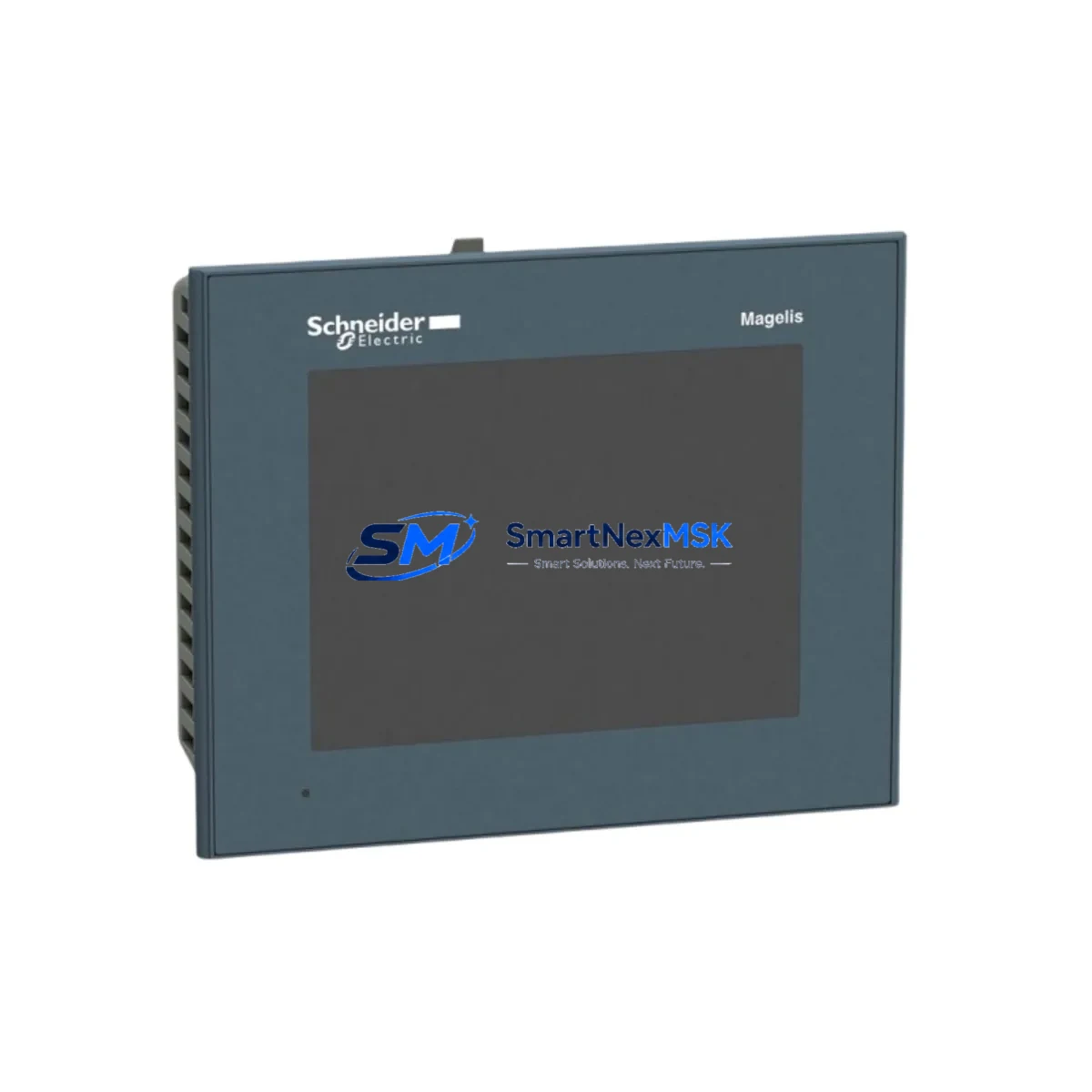
Where the original system used a Schneider XBTGT HMI or Magelis panel to display contactor status via auxiliary contact feedback, the LA1DN10 auxiliary contact block mounted on the LC1D65M7C provides the 1NO signal required for the PLC input card. Verify the input card’s voltage rating (typically 24V DC on a Modicon BMX DDI 1602 or similar discrete input module) matches the field wiring before reconnecting.
For facilities running Profibus DP or Modbus RTU communication networks, the LC1D65M7C itself is a passive switching device and does not require network reconfiguration. However, if the motor starter assembly includes a Tesys U or TeSys T motor management relay communicating over the fieldbus, the relay’s parameter set (FLA, trip class, communication address) must be re-entered after replacement to restore full remote monitoring capability.
Before closing the control cabinet, conduct a full point-to-point continuity check on all main and control terminals, verify DIN rail seating and mechanical interlock (if applicable), and perform a no-load energization test to confirm coil pull-in and drop-out at the correct voltage thresholds. All replacement components are pre-tested and shipped with inspection records to support your site acceptance procedure.
Downtime Control During System Migration
Minimizing production downtime during a contactor replacement requires a structured pre-outage preparation protocol. Before the scheduled maintenance window, stage the LC1D65M7C alongside all ancillary components — auxiliary contact blocks, overload relay, terminal ferrules, and updated wiring labels — so that the physical swap can be completed within a single shift. Where possible, pre-wire the new contactor on a temporary sub-plate and perform a bench test of coil operation and auxiliary contact continuity before the outage begins.
During the outage, isolate the motor feeder at the upstream MCCB or fused disconnect, lock out and tag out per site LOTO procedures, and photograph the existing wiring before removal. The LC1D65M7C’s terminal layout mirrors the outgoing TeSys D unit, so main power terminals (L1/L2/L3 → T1/T2/T3) and coil terminals (A1/A2) can be reconnected directly from the as-found wiring photograph without reference to the original drawing set — though drawing verification is always recommended.
To protect existing PLC program logic, do not modify any I/O address assignments or function block parameters during the hardware swap. The replacement contactor is a like-for-like functional substitute; no software changes to the Modicon M340, M580, or Premium PLC program are required. After reconnection, restore power in stages: energize the control circuit first, verify coil operation via the HMI or local pushbutton, then close the main feeder and confirm motor rotation direction before returning the process to automatic mode.
All LC1D65M7C units supplied are covered by a 12-month warranty from the date of shipment, covering coil failure, contact welding, and mechanical defects under normal operating conditions. Expedited shipping from in-stock inventory ensures that emergency replacement orders can be dispatched within 24 hours to minimize unplanned downtime exposure.
Retrofit Support FAQ
Q1: Is the LC1D65M7C a direct drop-in replacement for the LC1D65A or LC1D50M7C?
The LC1D65M7C shares the same frame size, DIN rail footprint, and terminal layout as other TeSys D 40–80A contactors. It is a direct mechanical replacement for the LC1D65A (with coil voltage change noted) and a functional upgrade from the LC1D50M7C in applications where the motor FLA is between 50A and 65A. Always verify coil voltage suffix and auxiliary contact configuration before ordering.
Q2: What commissioning checks are required after installation?
After installation, perform: (1) coil pull-in voltage test at 85% and 110% of rated voltage; (2) auxiliary contact continuity check at A1/A2 energized and de-energized states; (3) main contact resistance measurement (should be <1mΩ per pole); (4) overload relay trip test at 1.2× FLA if an LRD series relay is fitted; and (5) full-load motor run for 15 minutes to confirm thermal stability.
Q3: Can the existing LA1D auxiliary contact blocks be reused on the LC1D65M7C?
Yes. All LA1D series front-face auxiliary contact blocks (LA1DN10, LA1DN01, LA1DN11, LA1DK11, etc.) are mechanically and electrically compatible with the LC1D65M7C. The clip-on interface is standardized across the TeSys D range from LC1D09 through LC1D95. Inspect the existing blocks for contact wear and replace if contact resistance exceeds 100mΩ.
Q4: What does the 12-month warranty cover, and how is a claim processed?
The 12-month warranty covers manufacturing defects including coil open-circuit or short-circuit failure, main contact welding under rated load conditions, and mechanical latch failure. It does not cover damage from incorrect coil voltage, overcurrent beyond rated capacity, or improper installation. To initiate a warranty claim, contact [email protected] with the order number, installation date, and a description of the failure mode. Replacement units are dispatched from stock upon claim approval.
© 2026 SMARTNEXMSK. All rights reserved.
Original Source: https://smartnexmsk.com
Contact: [email protected] | +86 18259474341