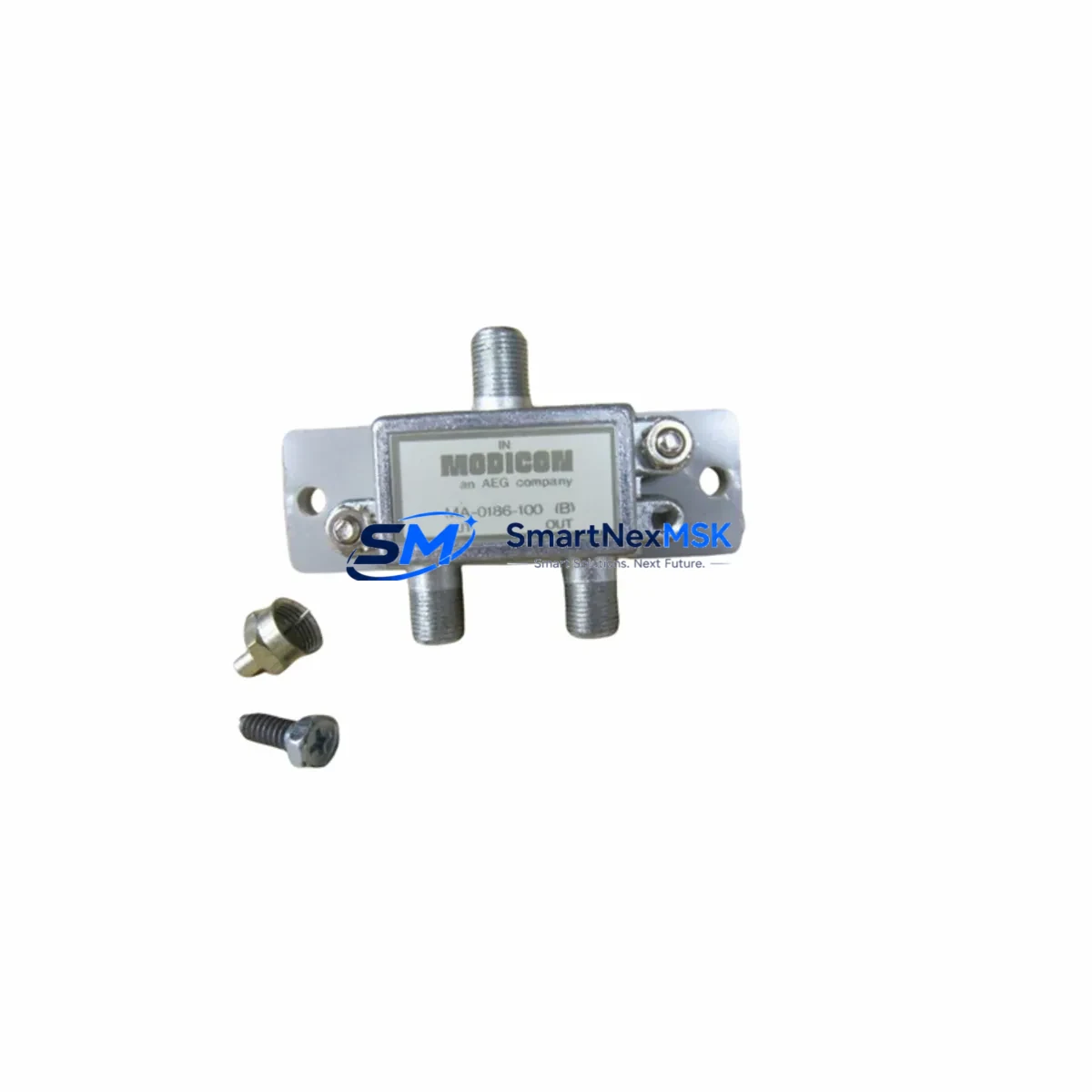
Schneider MA-0186-100 Retrofit-Ready MB+ Cable for Quantum Control Systems
The Schneider Electric MA-0186-100 is a Modbus Plus (MB+) coaxial network cable engineered for seamless integration into Modicon Quantum-series control architectures. As legacy Quantum systems approach end-of-life and original MB+ cabling becomes increasingly difficult to source, the MA-0186-100 serves as a verified retrofit-ready replacement that preserves existing network topology without requiring controller reprogramming or HMI screen redesign. Whether you are replacing a degraded segment in a running production line or rebuilding a control cabinet after a fault event, this cable delivers the electrical and mechanical specifications required for reliable MB+ peer-to-peer and drop communication.
Upgrade Compatibility Table
| Parameter | Detail |
|---|---|
| SKU / Part Number | MA-0186-100 |
| Brand | Schneider Electric (Modicon) |
| Series Compatibility | Modicon Quantum (S908 backplane), Modicon 984, Modicon Momentum |
| Network Protocol | Modbus Plus (MB+) — RS-485 coaxial topology |
| Cable Type | MB+ Coaxial, 100 ft (approx. 30 m) |
| Connector Interface | BNC / MB+ drop port compatible |
| Installation Requirement | Terminate both ends with 75 Ω BNC terminators; verify network node addressing before power-on |
| Replaces / Supersedes | Degraded or discontinued MB+ trunk and drop cable segments in Quantum cabinets |
| Retrofit Recommendation | Direct swap; no firmware change required if node count and addresses are preserved |
| Commissioning Focus | Node address conflict check, terminator resistance verification, MB+ traffic monitor scan |
| Warranty | 12 Months — covers manufacturing defects and electrical performance |
Retrofit Planning for Existing Automation Systems
Integrating the MA-0186-100 into an existing Quantum control system requires a structured pre-replacement audit. Begin by documenting the current MB+ network map: identify every node on the trunk, record the node addresses assigned to each 140CPU65160 or 140CPU67160 processor module, and confirm the drop cable routing from the trunk to each remote I/O drop adapter. In multi-rack installations, the 140XBP01600 or 140XBP00600 backplane chassis must be inspected for physical port condition before the new cable is routed.
Power supply capacity is a critical pre-check. The 140CPS11420 or 140CPS21400 power supply modules feeding the local rack must have sufficient headroom to support any additional I/O modules brought online during the upgrade. If the retrofit scope includes adding 140ACI04000 analog input modules or 140DDO35300 discrete output modules to expand I/O capacity, recalculate the rack power budget before commissioning.
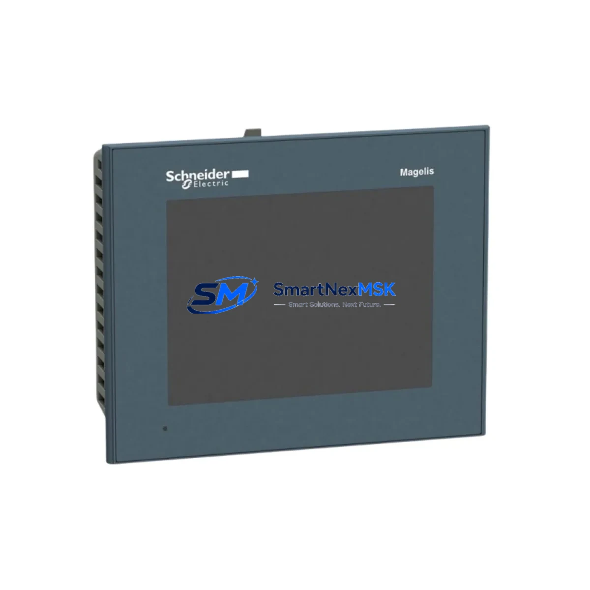
For systems that include a 140NOM21100 or 140NOE77101 Ethernet communication module alongside the MB+ network, verify that the new cable segment does not introduce ground loops or impedance mismatches that could degrade both networks simultaneously. If the control cabinet also houses a XBTGT5340 or similar Magelis HMI panel communicating over MB+, confirm that the HMI node address is excluded from the replacement segment’s node conflict scan before restoring power.
Programming cable access is recommended throughout the retrofit. Keep a TSXPCX3030 or USB-to-MB+ programming cable connected to the CPU port so that Unity Pro or Concept software can monitor the MB+ network health in real time during the cable swap. This allows immediate detection of any node that fails to re-establish communication after the new MA-0186-100 segment is terminated and energized.
Downtime Control During System Migration
Minimizing unplanned downtime during an MB+ cable replacement begins with a cold-standby preparation strategy. Before any physical disconnection, use Unity Pro’s online monitoring mode to capture a full snapshot of the MB+ network status, including node health, message error counters, and I/O table states. Export the application program from the 140CPU65160 to a backup file and store it on an offline engineering workstation — this ensures that if the CPU loses its program during a power interruption, recovery time is measured in minutes rather than hours.
Schedule the physical cable swap during a planned maintenance window. Isolate the affected MB+ segment by disconnecting the BNC drop connectors at both ends of the degraded cable run. Install the MA-0186-100 replacement segment, apply 75 Ω BNC terminators at both trunk ends, and perform a continuity check before reconnecting to the network. Power the rack back on in stages: energize the power supply first, confirm the CPU enters RUN mode, then verify that each remote I/O drop — including any 140CRA93100 remote I/O adapter — re-establishes its MB+ heartbeat within the expected scan cycle.
If the system includes redundant CPU configurations using a 140CPU67160 hot-standby pair, the cable replacement can be performed on the standby path first, validated, and then switched over — reducing the production impact to a single controlled switchover event rather than a full system shutdown. Throughout the process, maintain continuous HMI visibility on the XBTGT5340 operator panel to confirm that process values remain within normal operating ranges and that no safety interlocks are inadvertently triggered.
Retrofit Support FAQ
Q1: Is the MA-0186-100 a direct replacement for the original Schneider MB+ coaxial cable used in Quantum S908 systems?
Yes. The MA-0186-100 meets the same MB+ coaxial specification as the original factory cable. It is compatible with the S908 backplane drop port and all standard BNC MB+ connectors used in Quantum-series installations. No firmware update or controller reconfiguration is required provided that node addresses and network topology are preserved during installation.
Q2: What commissioning steps are required after installing the MA-0186-100?
After physical installation, verify terminator resistance at both trunk ends (75 Ω), perform a node address conflict scan using Unity Pro or Concept, and monitor MB+ error counters for a minimum of one full production cycle. If a 140NOM21100 communication module is present, confirm that MB+ traffic resumes on all configured nodes before releasing the system to production.
Q3: Can this cable be used in systems that are migrating from MB+ to Ethernet/IP?
Yes, during a phased migration. The MA-0186-100 maintains the existing MB+ backbone while Ethernet/IP infrastructure — such as the 140NOE77101 Ethernet module — is installed and validated in parallel. This allows the MB+ network to remain operational as the primary control path until the Ethernet/IP migration is fully commissioned and tested, eliminating the need for a single extended shutdown.
Q4: What does the 12-month warranty cover?
The 12-month warranty covers manufacturing defects, electrical performance failures, and connector integrity under normal industrial operating conditions. Each unit undergoes pre-shipment functional testing to verify cable continuity, impedance consistency, and connector seating. Warranty claims are supported by our technical team at [email protected] with a target response time of one business day.
© 2026 SMARTNEXMSK. All rights reserved.
Original Source: https://smartnexmsk.com
Contact: [email protected] | +86 18259474341