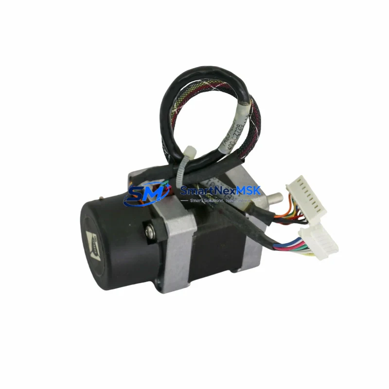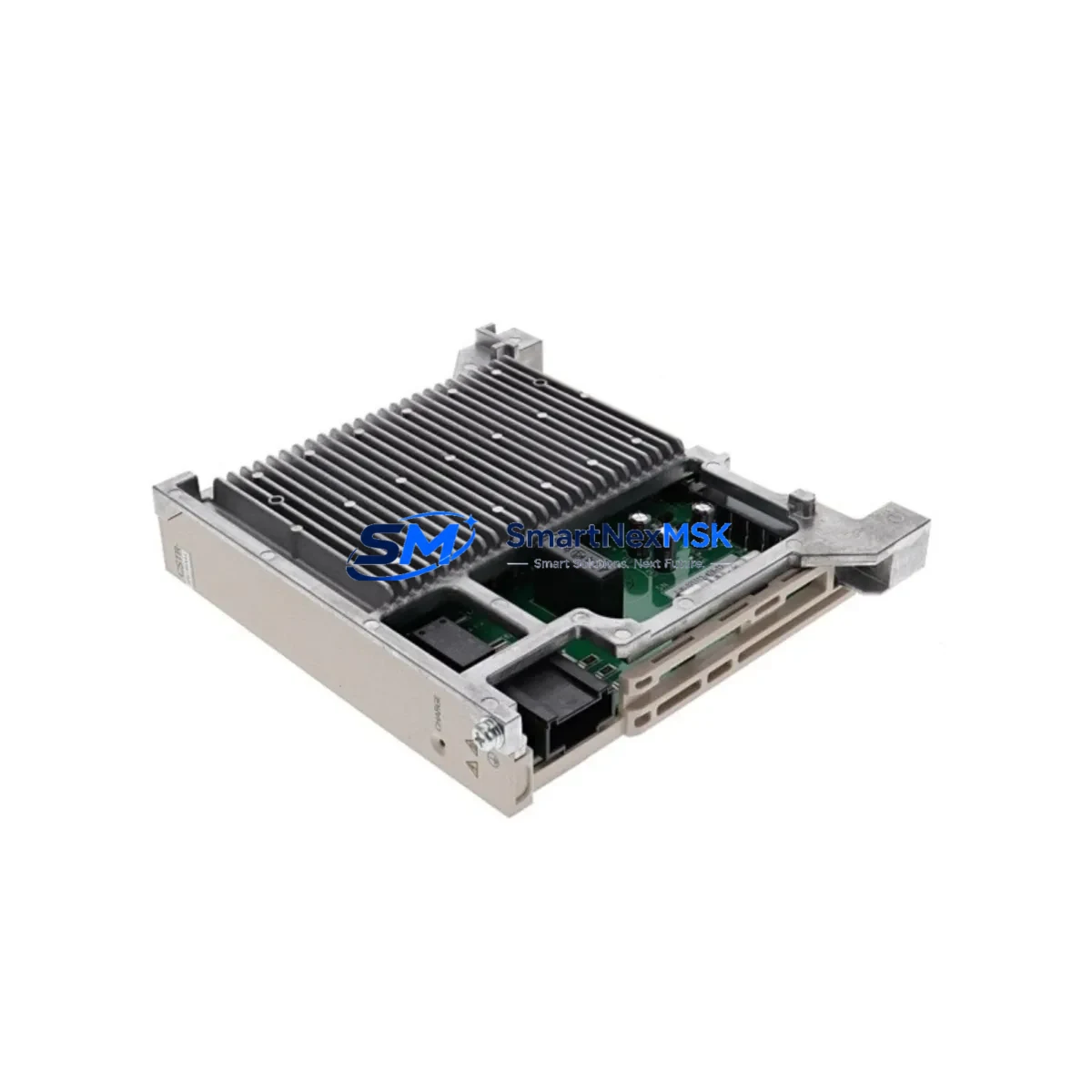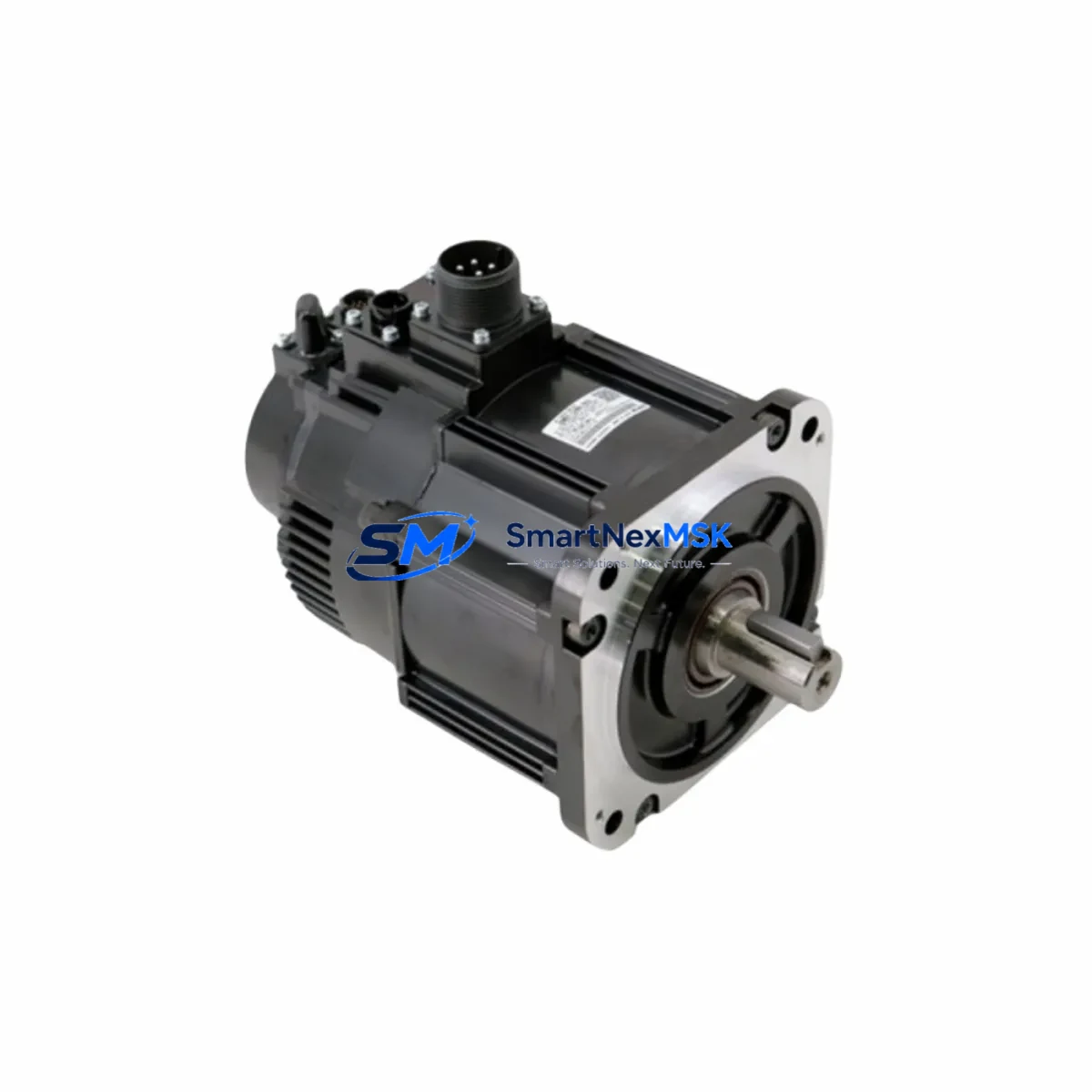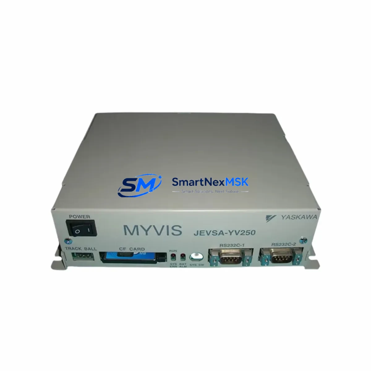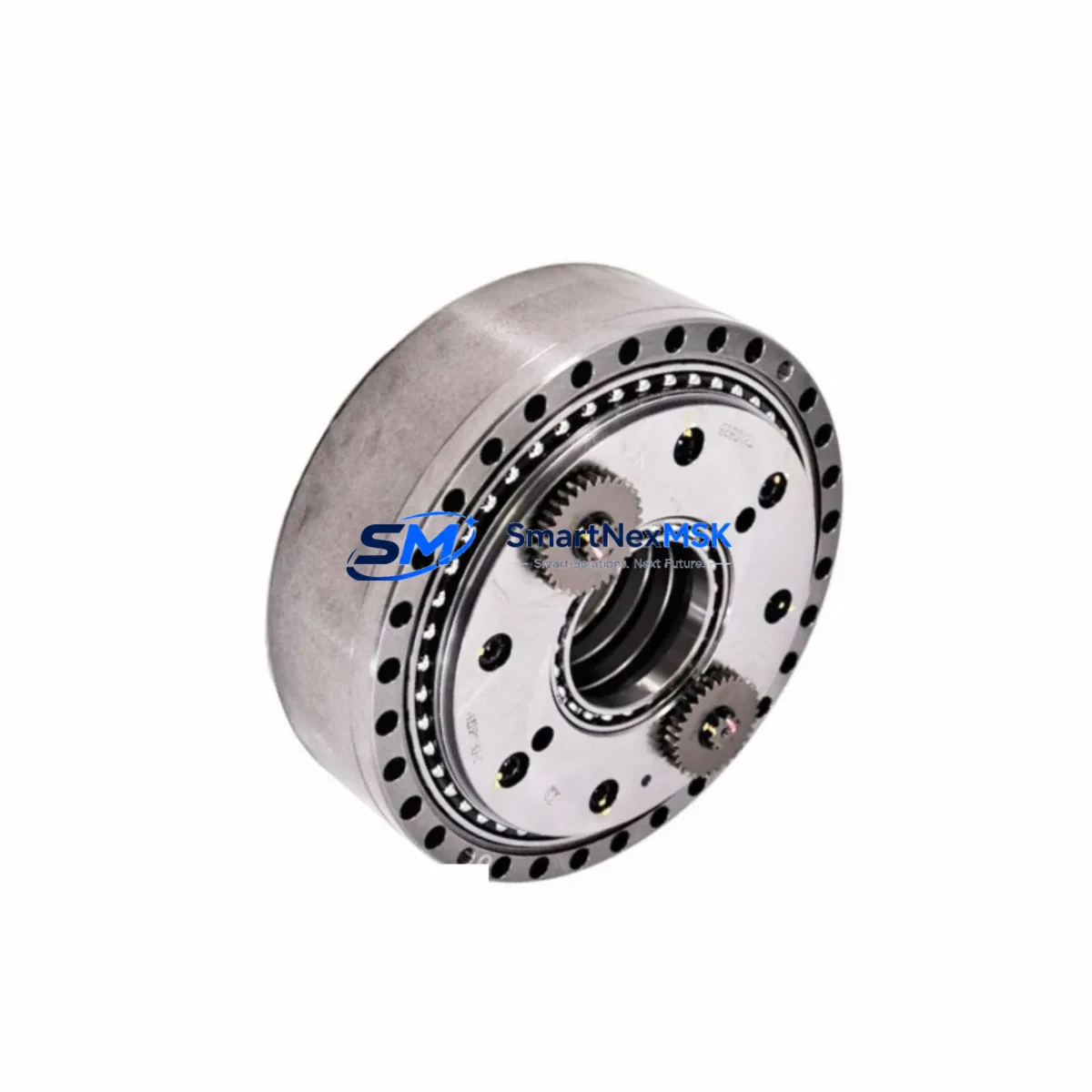
YASKAWA HW927381-A-12 Spare for Sigma/A1000 Automation: Braking Module Replacement & Downtime Control
The YASKAWA HW927381-A-12 regenerative braking module is a critical spare component for Sigma series servo systems and A1000 series AC drives deployed across manufacturing, process control, and motion automation environments. Whether you are managing a planned maintenance shutdown, responding to an unplanned drive fault, or building a strategic spare parts inventory for a multi-axis control cabinet, having a verified original HW927381-A-12 on hand is essential to minimizing mean time to repair (MTTR) and protecting production continuity.
This unit ships as an original YASKAWA spare — not a clone or remanufactured substitute — and is fully tested prior to dispatch. Alternate compatible part numbers include HW0389174-C and HW9381284-B, which may appear on legacy BOMs, MRO procurement lists, or OEM service documentation for the same drive family. All three references are cross-verified against YASKAWA’s Sigma and A1000 platform specifications before shipment.
Spare Maintenance Table
| Parameter | Specification / Detail |
|---|---|
| Part Number | HW927381-A-12 (alt: HW0389174-C, HW9381284-B) |
| Brand | YASKAWA |
| Compatible Series | Sigma Servo Series, A1000 AC Drive Series |
| Component Type | Regenerative Braking Module |
| Function | Dissipates regenerative energy during deceleration; protects DC bus from overvoltage faults |
| Mounting | Internal drive bay / control cabinet DIN rail (series-dependent) |
| Origin | Japan |
| Condition | Original spare, pre-shipment tested |
| Application Environment | Industrial automation, servo motion control, variable frequency drive systems |
| Compatibility Verification | Cross-referenced against Sigma and A1000 platform BOM |
| Maintenance Interval | Inspect every 12–24 months or upon DC bus overvoltage fault (OV alarm) |
| Warranty | 12 Months from date of shipment |
| Lead Time | In-stock; ships within 1–3 business days |
| Long-Term Supply | Available for repeat orders and MRO blanket agreements |
Maintenance Planning for Continuous Operation
When a regenerative braking module such as the HW927381-A-12 is flagged for replacement during a control cabinet inspection or after a drive fault event, experienced maintenance engineers know that the braking module rarely fails in isolation. A thorough site assessment should include the following adjacent components to prevent repeat failures and ensure the drive system returns to full operational health.
Begin with the YASKAWA A1000 main control board and gate driver board — overvoltage events that stress the braking module often leave thermal or electrical stress signatures on these boards. Inspect the DC bus capacitor bank for bulging, leakage, or elevated ESR, as degraded capacitors are a leading cause of recurring OV faults that accelerate braking module wear. Check the braking resistor (external or internal) for open-circuit or resistance drift; a failed resistor will cause the replacement HW927381-A-12 to fail prematurely under the same load cycle.
On the power input side, verify the input reactor or line filter for continuity and insulation integrity. Inspect input terminal blocks and power wiring for loose connections, discoloration, or signs of arcing — poor connections increase ripple current and thermal stress on the DC bus components. If the drive is part of a multi-axis system, check the YASKAWA MECHATROLINK-III or EtherCAT communication module for firmware version compatibility after any hardware replacement, as some drive firmware versions have known interactions with braking control parameters.
For the servo feedback loop, inspect the encoder cable and connector at both the motor and drive ends. A degraded encoder signal can cause erratic deceleration commands that repeatedly trigger the braking circuit beyond its rated duty cycle. Similarly, review the I/O terminal board and any safety relay or STO (Safe Torque Off) module wired into the drive’s enable circuit — nuisance trips from these circuits can mask underlying braking module stress.
Finally, if the cabinet houses a YASKAWA DriveWizard or PLC-integrated parameter backup unit, confirm that drive parameters (including braking duty cycle limits, OV trip levels, and deceleration ramp settings) are archived before and after the HW927381-A-12 replacement. This protects against parameter loss during power cycling and ensures the replacement module operates within its designed thermal envelope from first power-on.
Site Replacement Workflow
Step 1 — Fault Isolation: Record the active fault code (typically OV, UV, or braking fault) from the A1000 or Sigma drive operator panel or DriveWizard interface. Document the fault history log before clearing alarms.
Step 2 — Safe Isolation: De-energize the drive following LOTO (Lockout/Tagout) procedures. Wait a minimum of 5 minutes after power-off for DC bus capacitors to discharge below 25 VDC. Verify with a calibrated multimeter before opening the drive enclosure.
Step 3 — Module Removal: Photograph wiring and connector positions before disconnecting. Remove the HW927381-A-12 (or its equivalent HW0389174-C / HW9381284-B) by releasing the retaining clips or screws per the YASKAWA service manual for the specific drive frame size.
Step 4 — Inspection & Cleaning: Inspect the module bay for carbon deposits, moisture ingress, or damaged bus bar contacts. Clean with dry compressed air or isopropyl alcohol as appropriate before installing the replacement unit.
Step 5 — Installation & Verification: Install the replacement HW927381-A-12, reconnect all connectors to their original positions, and torque terminal screws to the manufacturer’s specification. Restore power and perform a no-load test run, monitoring DC bus voltage and braking duty cycle via the drive’s diagnostic display or DriveWizard software.
Step 6 — Parameter Restore & Commissioning: Restore archived parameters if required. Run a loaded test cycle at reduced speed before returning the axis to full production duty. Log the replacement date, part number, and technician ID in the site maintenance record.
This workflow is applicable whether you are replacing a failed unit on an emergency basis or performing a scheduled swap as part of a predictive maintenance program. Keeping one or two HW927381-A-12 units in your on-site spare parts store eliminates the lead-time risk associated with emergency procurement and supports a proactive maintenance culture.
Spare Parts Support FAQ
Q1: Is the HW927381-A-12 a direct drop-in replacement for HW0389174-C and HW9381284-B?
Yes. All three part numbers refer to the same regenerative braking module within the YASKAWA Sigma and A1000 platform. They may appear under different revision suffixes on legacy BOMs or regional service documentation, but are functionally and dimensionally interchangeable. We cross-verify all three references before shipment to confirm compatibility with your specific drive frame and firmware revision.
Q2: How is the unit tested before shipment?
Each HW927381-A-12 unit undergoes pre-shipment functional testing covering insulation resistance, switching element integrity, and thermal performance under simulated load conditions. A test report is available upon request. The unit ships with a 12-month warranty covering manufacturing defects and functional failure under normal operating conditions.
Q3: Can I order multiple units for a blanket spare parts inventory?
Yes. We support MRO blanket orders and repeat procurement agreements for maintenance teams managing multiple Sigma or A1000 drive installations. Volume pricing and reserved stock arrangements are available — contact [email protected] or call +86 18259474341 to discuss your site’s spare parts strategy.
Q4: What is the recommended spare parts holding strategy for this module?
For facilities operating more than three A1000 or Sigma drives in continuous production, we recommend holding a minimum of one HW927381-A-12 per five drives as a strategic on-site spare. For critical single-axis applications where downtime cost is high, a 1:1 spare ratio is advisable. Modules stored in a dry, temperature-controlled environment retain full serviceability for 3–5 years without special conditioning.
© 2026 SMARTNEXMSK. All rights reserved.
Original Source: https://smartnexmsk.com
Contact: [email protected] | +86 18259474341