
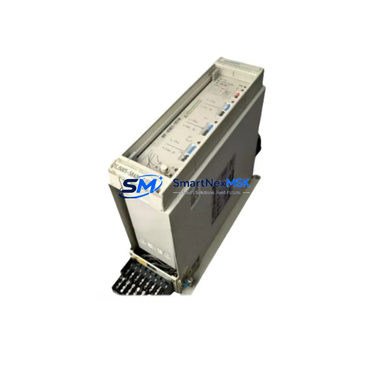
YOKOGAWA 7SJ5005-5CA00/FF Retrofit-Ready Digital Input Module for STARDOM FCN/FCJ Control Systems
The YOKOGAWA 7SJ5005-5CA00/FF is a Digital Input Module engineered for seamless integration into STARDOM FCN and FCJ distributed control node architectures. As legacy automation infrastructure ages and OEM support windows close, this module serves as a verified drop-in replacement for discontinued DI modules within the STARDOM platform — enabling plant engineers to restore full I/O capacity without redesigning the control cabinet or rewriting application logic.
Whether you are managing a scheduled turnaround, responding to an unplanned module failure, or executing a phased control system upgrade, the 7SJ5005-5CA00/FF provides the electrical compatibility, form factor match, and firmware recognition required to minimize engineering risk and compress commissioning time. The module is sourced from verified supply channels, undergoes pre-shipment functional testing, and is backed by a 12-month warranty covering manufacturing defects and operational failures under normal service conditions.
Upgrade Compatibility Table
| Parameter | Details |
|---|---|
| Module Type | Digital Input (DI) |
| Compatible Platform | YOKOGAWA STARDOM FCN / FCJ |
| Backplane Interface | STARDOM FCN standard module bus |
| Installation Format | Direct slot replacement — no adapter required |
| Communication Compatibility | FOUNDATION Fieldbus (FF); compatible with FCN node communication stack |
| Replacement Scope | Drop-in for discontinued STARDOM DI modules of equivalent channel count and signal type |
| Wiring Adaptation | Terminal block pinout matches legacy STARDOM DI wiring standard; verify field wiring polarity before power-up |
| Commissioning Requirement | Module address assignment via FCN Engineering Tool; I/O tag mapping verification recommended |
| Program Compatibility | Existing FCN application logic and HMI tag references remain valid; no recompilation required in standard retrofit scenarios |
| Warranty | 12 months from shipment date — covers manufacturing defects and operational failures under normal service conditions |
Retrofit Planning for Existing Automation Systems
A successful retrofit of the 7SJ5005-5CA00/FF into an operating STARDOM FCN system begins well before the module arrives on site. Engineers should start by auditing the FCN node’s current slot population, confirming available backplane capacity, and verifying that the power supply module — typically the YOKOGAWA FCN-100 or FCN-500 series power unit — can support the additional load introduced by the replacement DI module. Power budget calculations should account for all installed I/O modules, the FCN CPU module, and any communication modules sharing the same rack.
Terminal wiring is the next critical checkpoint. The 7SJ5005-5CA00/FF uses the standard STARDOM DI terminal block layout, but field cables connected to the legacy module must be inspected for insulation condition, correct labeling, and polarity. In older installations where the YOKOGAWA NF8S-SB or equivalent signal barrier modules are used for intrinsic safety isolation, confirm that the barrier specifications remain within the input threshold range of the replacement module.
For systems where the FCN node communicates upstream via FOUNDATION Fieldbus to a YOKOGAWA CENTUM VP or ProSafe-RS safety controller, the communication link configuration stored in the FCN Engineering Tool should be exported and archived before any hardware change. This preserves the segment topology, device tag assignments, and macrocycle timing parameters that govern the FF communication between the FCN node and field devices such as YOKOGAWA EJX series pressure transmitters or YTA series temperature transmitters.
Where the control system includes a YOKOGAWA Exaopc OPC server or a third-party SCADA connected via Modbus TCP, verify that the I/O address map used by the supervisory layer correctly references the DI channel addresses assigned to the 7SJ5005-5CA00/FF after module installation. Address conflicts between the new module and any remaining legacy modules in adjacent slots can cause silent data errors that are difficult to diagnose during live operation.
If the retrofit scope extends beyond a single DI module replacement — for example, when simultaneously upgrading analog input modules such as the YOKOGAWA AAI141 or AAI543, or adding a new communication module for Ethernet/IP connectivity — a staged slot-by-slot replacement plan reduces the risk of simultaneous multi-point failures. Each module should be commissioned and verified independently before the next replacement proceeds.
Downtime Control During System Migration
Minimizing production downtime during a STARDOM FCN module replacement requires a structured pre-outage preparation protocol. Before the maintenance window opens, the FCN application program should be exported from the FCN Engineering Tool and stored on an offline backup medium. This ensures that if the replacement module triggers an unexpected node restart or configuration mismatch, the original program can be reloaded within minutes rather than hours.
During the physical swap, the FCN node should be placed in a controlled stop state using the FCN Engineering Tool’s online mode, with all output modules confirmed in their safe de-energized state before the DI module is removed. Because the 7SJ5005-5CA00/FF is a digital input module, its removal does not directly affect output-driven actuators, but the loss of input signals may trigger interlock logic in the FCN application or in a connected ProSafe-RS safety system. Interlock bypass procedures should be authorized and documented before work begins.
After physical installation, the module address is assigned through the FCN Engineering Tool’s hardware configuration view. Once the address is confirmed and the node is returned to run mode, each DI channel should be verified against the field signal source — typically by toggling the connected field device or using a loop calibrator — to confirm that the FCN application is receiving correct ON/OFF state data. HMI faceplate displays connected to the YOKOGAWA FAST/TOOLS or Exaquantum historian should be checked to confirm that the tag values are updating correctly and that no alarm floods are generated by the newly installed module.
For sites operating under IEC 61511 functional safety requirements, the post-replacement proof test record for the DI channel must be updated to reflect the new module serial number and the date of the validated channel test. This documentation is required for SIL compliance audits and should be filed in the plant’s safety instrumented system management records.
Retrofit Support FAQ
Q: Is the 7SJ5005-5CA00/FF a direct replacement for my existing STARDOM FCN DI module?
A: In the majority of STARDOM FCN retrofit scenarios, the 7SJ5005-5CA00/FF installs directly into the vacated slot without mechanical or wiring modification. However, you should verify the channel count, input voltage range, and terminal block type of the module being replaced against the 7SJ5005-5CA00/FF datasheet before ordering. If your legacy module used a different terminal block style, a YOKOGAWA-compatible terminal adapter may be required.
Q: Do I need to modify my FCN application program after installing this module?
A: In standard replacement scenarios where the module type and channel count are identical, no program modification is required. The FCN application logic references I/O tags by address, not by module serial number. After assigning the correct module address in the FCN Engineering Tool hardware configuration, the existing tag assignments will map correctly to the new module’s channels. A full I/O channel verification test is still recommended before returning the system to automatic control.
Q: What pre-shipment testing is performed on the 7SJ5005-5CA00/FF?
A: Each unit undergoes functional verification prior to shipment, including digital input channel response testing across the specified input voltage range and backplane communication interface validation. Units that fail any test parameter are quarantined and not shipped. The 12-month warranty covers failures attributable to manufacturing defects or component quality issues identified during normal service operation.
Q: What should I do if the FCN node does not recognize the replacement module after installation?
A: First, confirm that the module is fully seated in the backplane slot and that the slot address in the FCN Engineering Tool hardware configuration matches the physical slot position. If the node still does not recognize the module, perform a controlled node restart from the FCN Engineering Tool and re-download the hardware configuration. If the issue persists, contact our technical support team with the FCN node model, firmware version, and the hardware configuration file for further diagnosis.
© 2026 SMARTNEXMSK. All rights reserved.
Original Source: https://smartnexmsk.com
Contact: [email protected] | +86 18259474341



