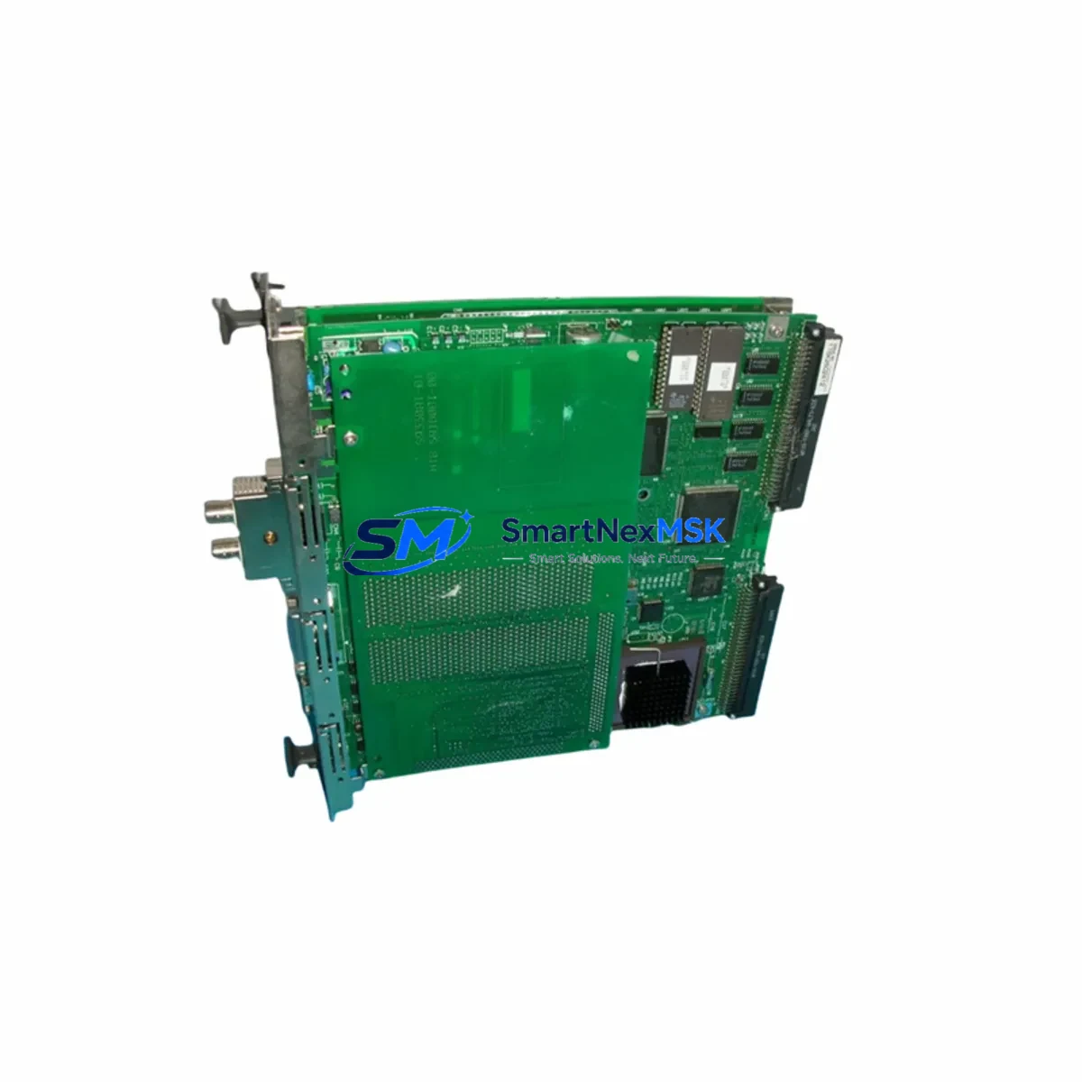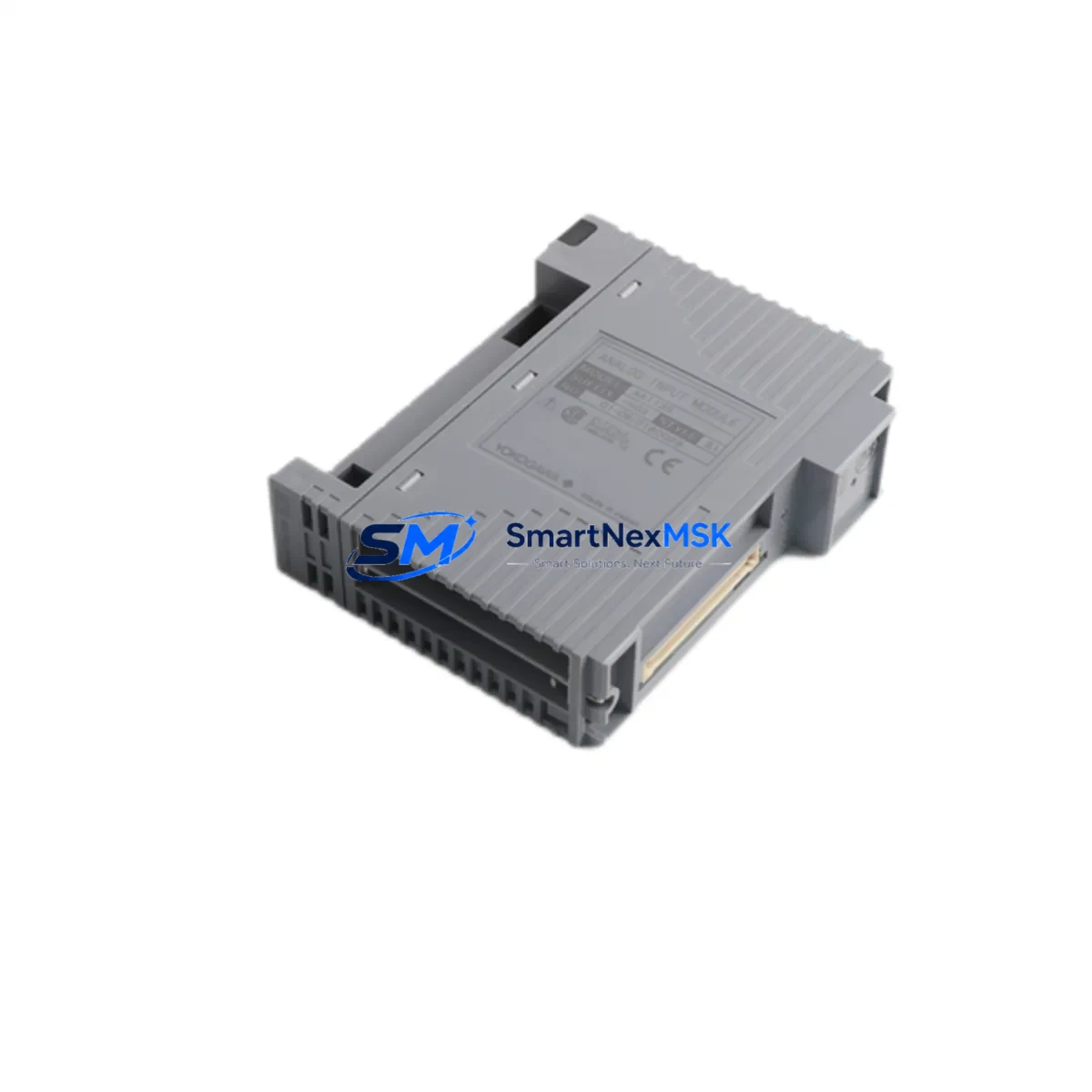
YOKOGAWA AAI135-H03 S1 Maintenance-Ready Spare CENTUM VP: Spare Replacement & Industrial Downtime Risk Control
The YOKOGAWA AAI135-H03 S1 is a 16-channel analog input module designed for the CENTUM VP distributed control system — one of the most widely deployed DCS platforms in process industries including oil & gas, petrochemical, power generation, and pharmaceutical manufacturing. As a maintenance-ready original spare, this module is sourced, inspected, and dispatched to support rapid field replacement, minimizing unplanned downtime and protecting continuous production operations.
For maintenance engineers managing aging CENTUM VP control cabinets, the AAI135-H03 S1 represents a critical line item in any structured spare parts inventory. Its 16-channel 4–20 mA analog input capability handles field instrument signals from pressure transmitters, flow meters, temperature sensors, and level gauges — making it a high-impact component whose failure can cascade across entire process loops. Procurement engineers sourcing this module should prioritize verified original units with documented compatibility, functional test records, and a minimum 12-month warranty to align with plant maintenance cycles.
Spare Maintenance Table
| Parameter | Specification |
|---|---|
| Part Number / SKU | AAI135-H03 S1 |
| Brand | YOKOGAWA |
| Series / Platform | CENTUM VP DCS |
| Module Type | Analog Input Module (16-Channel) |
| Signal Type | 4–20 mA (Current Input) |
| Channel Count | 16 Channels |
| Compatibility | CENTUM VP, CENTUM CS 3000 (verify revision) |
| Installation | Field Control Station (FCS) I/O Nest, DIN-rail backplane |
| Operating Environment | Industrial process control cabinets; 0–55°C ambient |
| Origin | Japan (Original YOKOGAWA) |
| Weight | 320 g |
| Maintenance Recommendation | Replace on signal drift >0.1% FS, channel failure, or scheduled 5-year overhaul |
| Warranty | 12 Months — Functional test verified before dispatch |
Maintenance Planning for Continuous Operation
When replacing the AAI135-H03 S1 in a live CENTUM VP system, a disciplined maintenance workflow requires more than a module swap. Maintenance engineers should treat this replacement as a trigger for a broader cabinet inspection to prevent secondary failures and ensure loop integrity is fully restored.
Begin by verifying the ALF111 field bus coupler or equivalent communication interface connecting the I/O nest to the FCS processor — a degraded coupler can cause intermittent channel faults that mimic analog input module failure. Inspect the PW481 or PW482 power supply module supplying the I/O nest; voltage sag or ripple on the 24 VDC rail is a common root cause of analog input drift and should be measured before the new AAI135-H03 S1 is commissioned.
Check the terminal block assemblies and field wiring terminations at the I/O marshalling panel. Corroded or loose terminals on 4–20 mA loops introduce offset errors that will persist even after a module replacement. If the cabinet includes signal isolators or loop-powered barriers (such as YOKOGAWA MTL or equivalent Zener barriers for hazardous area loops), verify their output compliance voltage and isolation integrity — these components age independently of the I/O module and are frequently overlooked during spare part replacements.
For systems with AAI141 or AAI143 analog input modules installed in adjacent slots, cross-check their channel diagnostics in the CENTUM VP engineering station. A failing AAI135-H03 S1 can sometimes indicate a broader I/O nest issue affecting neighboring modules. Similarly, if the control loop includes AO (analog output) modules such as the AAO145 driving control valves, verify their output calibration after the input module is replaced to confirm the full control loop is functioning correctly.
Where the CENTUM VP system interfaces with a STARDOM FCN/FCJ remote I/O node or communicates via Vnet/IP or FOUNDATION Fieldbus H1 segments, confirm that the communication health indicators in the HIS (Human Interface Station) show no residual alarms after module hot-swap. Finally, inspect the ESB bus connectors and I/O nest backplane for oxidation or mechanical damage — backplane contact issues are a leading cause of repeat module failures in high-humidity or coastal industrial environments.
Site Replacement Workflow
Step 1 — Pre-Replacement Verification: Confirm the replacement AAI135-H03 S1 suffix code (H03, S1) matches the installed unit exactly. Suffix codes in YOKOGAWA CENTUM VP modules encode hardware revision and I/O configuration — mismatched suffixes may cause system recognition errors or require engineering station reconfiguration.
Step 2 — Loop Isolation: Place affected control loops in manual mode at the HIS before removing the module. For critical process loops (reactor feed, compressor surge control), coordinate with the control room operator and follow site MOC (Management of Change) procedures.
Step 3 — Hot-Swap Execution: The CENTUM VP FCS supports online module replacement (hot-swap) without FCS restart in most configurations. Remove the faulty AAI135-H03 S1, insert the replacement, and allow the FCS to auto-recognize the module — typically within 30–60 seconds. Verify channel status in the engineering station before returning loops to automatic.
Step 4 — Post-Replacement Loop Check: Perform a full 4–20 mA loop check on all 16 channels using a calibrated loop calibrator. Compare live readings against the historian trend to confirm signal accuracy is restored. Document the replacement in the plant CMMS with the new module serial number and test results.
Step 5 — Spare Stock Replenishment: After consuming a spare AAI135-H03 S1, initiate a replenishment order immediately. Plants operating CENTUM VP systems with 10+ years of service life should maintain a minimum of 2 units on-shelf to cover both planned overhaul and emergency replacement scenarios.
Spare Parts Support FAQ
Q1: Is this AAI135-H03 S1 an original YOKOGAWA module or a compatible replacement?
This is an original YOKOGAWA AAI135-H03 S1 module — not a third-party compatible or remanufactured unit. Each unit is sourced from verified supply channels, functionally tested prior to dispatch, and supplied with a 12-month warranty covering manufacturing defects and functional failure under normal operating conditions.
Q2: How do I confirm compatibility with my installed CENTUM VP system version?
Compatibility depends on your FCS hardware generation and CENTUM VP software revision. The AAI135-H03 S1 is compatible with CENTUM VP R5.x and R6.x FCS configurations using standard ESB bus I/O nests. For CENTUM CS 3000 systems, verify the nest type and FCS model before ordering. Our technical team can assist with compatibility confirmation if you provide your FCS model number and system revision.
Q3: What testing is performed before the module is shipped?
Every AAI135-H03 S1 unit undergoes functional verification including power-on self-test, channel continuity check across all 16 analog input channels, and signal accuracy verification at 4 mA, 12 mA, and 20 mA reference points. Units that fail any test parameter are quarantined and not dispatched. Test records are available upon request for quality-critical procurement processes.
Q4: What is the lead time and long-term supply availability for this module?
In-stock units are dispatched within 1–3 business days with full export documentation. For long-term supply planning, we support blanket order arrangements and scheduled delivery programs for plants requiring annual or biennial spare part replenishment. The AAI135-H03 S1 remains an active procurement item in our YOKOGAWA CENTUM VP spare parts catalog, with supply continuity supported through 2028 and beyond based on current inventory and sourcing pipeline.
© 2026 SMARTNEXMSK. All rights reserved.
Original Source: https://smartnexmsk.com
Contact: [email protected] | +86 18259474341