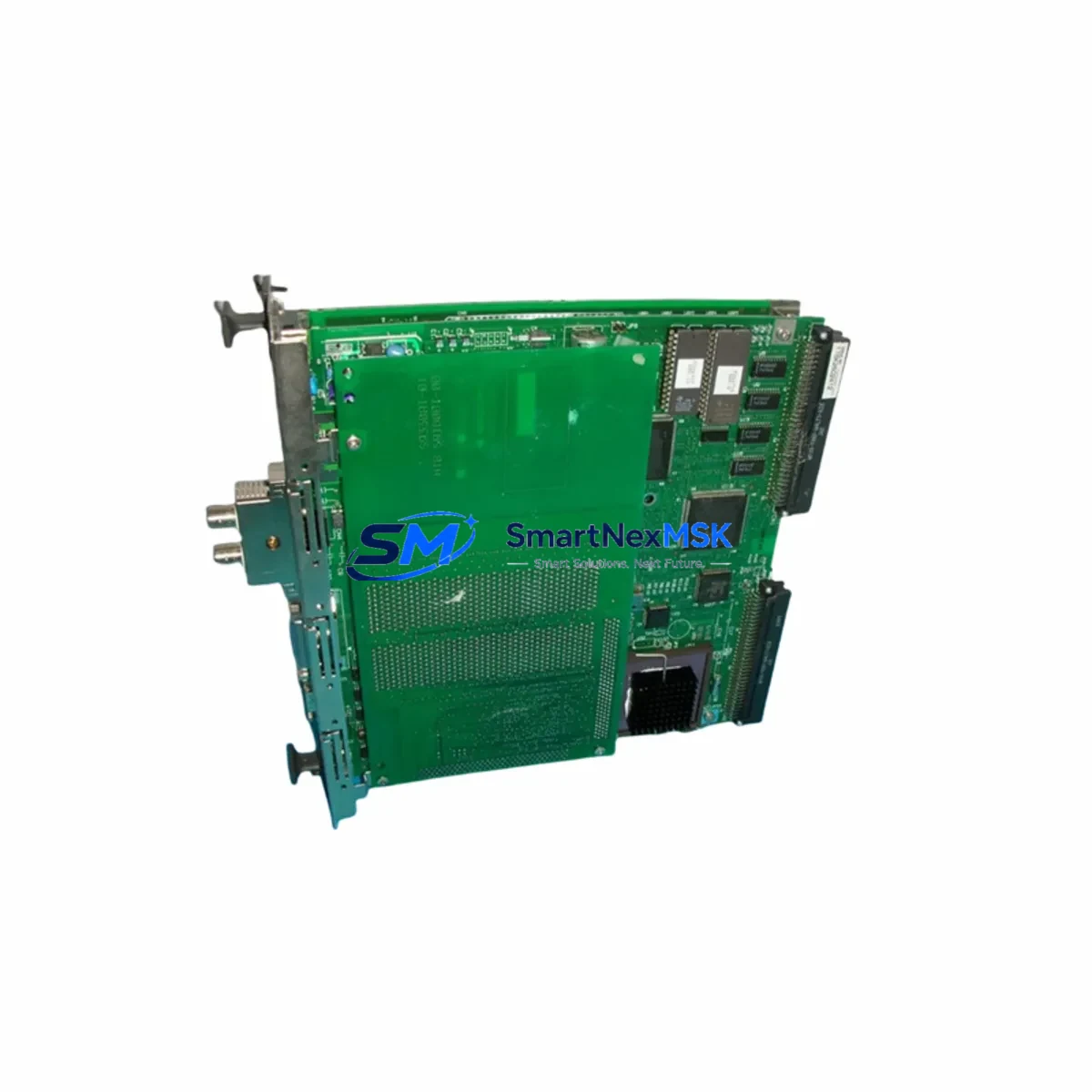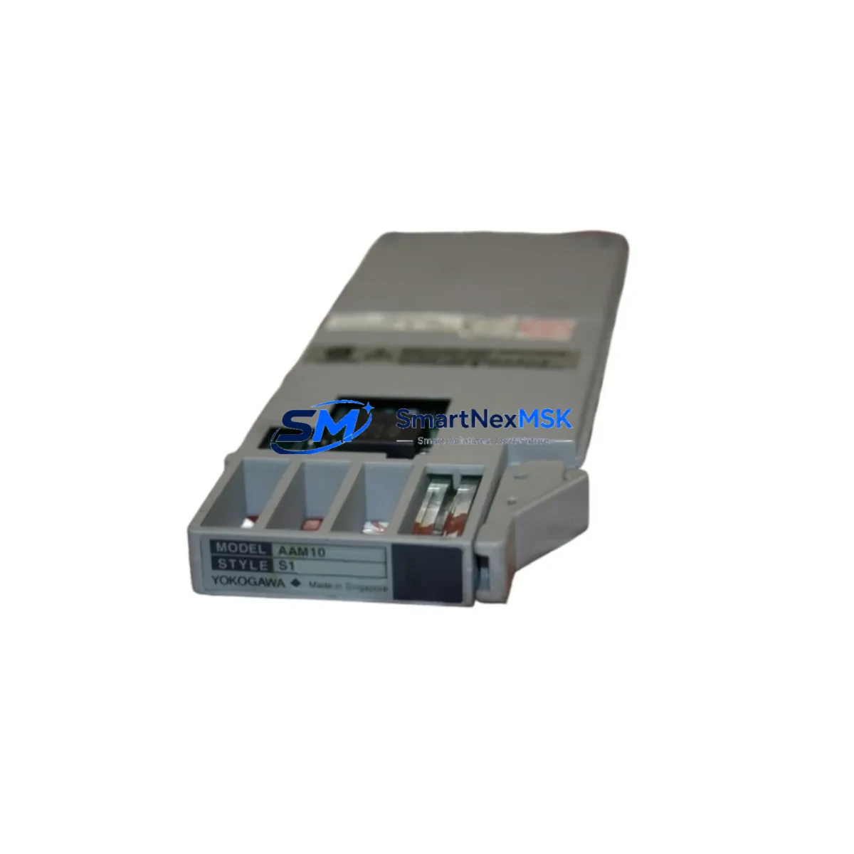
YOKOGAWA AAM10 Retrofit-Ready Analog Input for CENTUM Control Systems
The YOKOGAWA AAM10 is a high-precision analog input module engineered for seamless integration into CENTUM VP and CENTUM CS 3000 distributed control systems. As legacy DCS installations age and OEM support windows close, the AAM10 has become a critical retrofit component for facilities seeking to extend the operational life of their existing control infrastructure without committing to a full platform migration. Whether you are replacing a failed card, upgrading a degraded I/O subsystem, or consolidating a multi-vendor control cabinet, the AAM10 delivers the signal fidelity and protocol compatibility required for uninterrupted process control.
Designed to mount directly into standard YOKOGAWA field control station (FCS) baseplates, the AAM10 accepts 4–20 mA and 1–5 V analog signals across its input channels, making it a direct functional replacement for earlier-generation analog input cards used in CENTUM-series installations. Engineers migrating from discontinued modules such as the AAM11 or AAM21 will find that the AAM10 preserves existing terminal wiring layouts, reducing field rewiring time and minimizing the risk of signal errors during cutover. The module communicates natively over Vnet/IP and supports legacy RS-485 links, ensuring backward compatibility with older FCS configurations and HMI communication paths.
Upgrade Compatibility Table
| Parameter | Details |
|---|---|
| Compatible DCS Platforms | CENTUM VP, CENTUM CS 3000, CENTUM CS 1000 |
| Direct Replacement For | AAM11, AAM21, legacy CENTUM analog input cards |
| Mounting / Installation | Standard YOKOGAWA FCS baseplate (node unit rack) |
| Communication Protocols | Vnet/IP (primary), RS-485 (legacy link) |
| Signal Input Range | 4–20 mA / 1–5 V DC analog |
| Terminal Wiring Compatibility | Compatible with existing field terminal assemblies; verify marshalling cabinet wiring before cutover |
| Module Address Configuration | Set via CENTUM Engineering Environment (CAMS for HIS); confirm node and slot address before power-on |
| HMI / HIS Compatibility | YOKOGAWA HIS (Human Interface Station) with CENTUM VP or CS 3000 builder; no HMI screen rebuild required for like-for-like replacement |
| Commissioning Requirement | Download revised FCS database; perform loop check on all active channels; verify alarm setpoints |
| Warranty | 12 Months — covers manufacturing defects; pre-shipment functional test included |
Retrofit Planning for Existing Automation Systems
Successful AAM10 retrofits begin well before the module arrives on site. The first step is a thorough audit of the existing FCS node configuration using the CENTUM VP Engineering Environment or the legacy CAMS for HIS builder tool. Engineers should export the current FCS database, document all active I/O assignments, and verify that the target slot address is free or can be reassigned without disrupting adjacent control loops.
Power budget verification is equally critical. The YOKOGAWA PW481 or PW482 power supply modules feeding the node unit rack must have sufficient headroom to support the AAM10’s operating current draw alongside existing modules. In high-density racks where AAM50 (analog output) and ADM12 (digital input) modules are already installed, a power margin check should be completed before insertion.
Terminal wiring from the field marshalling cabinet to the FCS I/O baseplate should be verified against the original loop drawings. In many CENTUM CS 3000 installations, field signals are routed through TB series terminal blocks and MTL or P+F isolator barriers before reaching the analog input card. These intermediate components should be inspected for insulation degradation and contact resistance, particularly in installations exceeding 10 years of service.
For facilities running FOUNDATION Fieldbus or HART instruments alongside conventional 4–20 mA loops, confirm that the AAM10 slot assignment does not conflict with any ALF111 FOUNDATION Fieldbus communication modules or AIP588 HART multiplexer cards sharing the same node. Module address conflicts at the FCS level are a common source of commissioning delays and must be resolved in the engineering database before the new card is powered.
Where the retrofit scope extends beyond a single card replacement — for example, when upgrading an entire FCS node from CENTUM CS 3000 to CENTUM VP — the YOKOGAWA ACM12 communication module and ESB bus coupler assignments should also be reviewed. Migrating the Vnet/IP segment configuration and updating the CENTUM VP R6 FCS builder project file ensures that the new AAM10 is recognized correctly by the supervisory control layer and that historian tags mapped in the Exaquantum or third-party SCADA system continue to resolve without manual re-mapping.
Finally, pre-shipment testing at our facility includes a functional channel verification under simulated 4–20 mA input conditions, ensuring that every AAM10 shipped is confirmed operational before it reaches your control room. All units are supplied with a 12-month warranty covering manufacturing defects, with documentation available upon request.
Downtime Control During System Migration
Minimizing unplanned downtime during an AAM10 swap-out requires a structured hot-cutover or cold-standby strategy, depending on the criticality of the loops served by the module. For non-critical monitoring loops, a planned cold swap during a scheduled maintenance window is the lowest-risk approach: isolate the FCS node, remove the failed card, insert the AAM10, restore power, and download the updated FCS database from the engineering station.
For critical process control loops — such as reactor temperature inputs or compressor surge control signals — a parallel wiring strategy is recommended. Temporary signal jumpers can be used to route the 4–20 mA field signals to a portable loop calibrator or a spare analog input channel on an adjacent AAM10 or AAM50 module while the primary slot is serviced. This approach keeps the control loop active and prevents the FCS from driving outputs to their failsafe state during the card exchange.
Once the replacement AAM10 is seated and the FCS database is downloaded, perform a channel-by-channel loop check using a HART communicator or a precision milliamp source. Verify that each channel’s process variable (PV) reading in the YOKOGAWA HIS operator station matches the injected test signal within the module’s specified accuracy band. Confirm that alarm annunciation, interlock logic, and historian tag updates are functioning correctly before releasing the loop back to automatic control.
Maintaining a documented rollback procedure — including a backup copy of the pre-retrofit FCS database stored on the engineering station and a spare module held in the control room — ensures that any unexpected compatibility issue can be resolved within a single shift, keeping total migration downtime well within a four-hour maintenance window for most CENTUM installations.
Retrofit Support FAQ
Q1: Is the AAM10 a direct drop-in replacement for the AAM11 and AAM21 in CENTUM CS 3000 systems?
The AAM10 is functionally compatible with the analog input roles performed by the AAM11 and AAM21 in CENTUM CS 3000 and CENTUM VP installations. Terminal wiring layouts are generally preserved, but engineers should verify the FCS database slot assignment and confirm that the module firmware revision is supported by the installed CENTUM VP or CS 3000 software version before cutover.
Q2: What commissioning steps are required after installing the AAM10?
After physical installation, download the updated FCS database from the CENTUM engineering station, perform a full loop check on all active channels using a calibrated milliamp source, verify alarm setpoints and interlock assignments in the FCS builder, and confirm PV display accuracy at the HIS operator station. A pre-shipment functional test report is available upon request.
Q3: Can the AAM10 operate on both Vnet/IP and RS-485 communication links?
Yes. The AAM10 supports both Vnet/IP (the primary communication bus for CENTUM VP) and legacy RS-485 links used in older CENTUM CS 3000 and CS 1000 node configurations. Confirm the active communication link type in the FCS engineering database before installation to ensure the module is configured for the correct bus segment.
Q4: What does the 12-month warranty cover, and is pre-shipment testing included?
The 12-month warranty covers manufacturing defects identified under normal operating conditions. Every AAM10 unit undergoes a pre-shipment functional test simulating 4–20 mA input signals across all channels before dispatch. Test documentation is available upon request. Warranty claims are processed via our technical support team at [email protected].
© 2026 SMARTNEXMSK. All rights reserved.
Original Source: https://smartnexmsk.com
Contact: [email protected] | +86 18259474341