
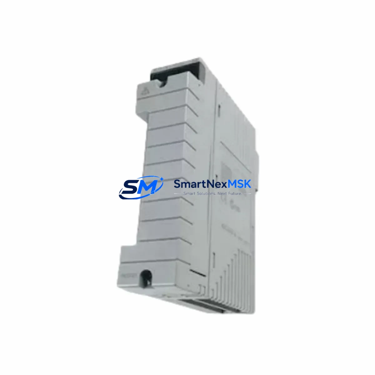
YOKOGAWA ADV551-P03 Maintenance-Ready Spare CENTUM VP Automation
The YOKOGAWA ADV551-P03 is a 32-channel digital output module designed for the CENTUM VP distributed control system. For maintenance engineers managing continuous-process plants — refineries, chemical facilities, power generation, and pulp & paper operations — unplanned downtime caused by a failed DO module can cascade into production losses within minutes. Stocking a verified original spare of the ADV551-P03 is one of the most cost-effective strategies for protecting uptime in CENTUM VP-based control architectures.
This listing supplies the ADV551-P03 as a maintenance-ready, original spare part. Each unit is sourced from authorized channels, inspected prior to dispatch, and shipped with a 12-month warranty covering manufacturing defects and functional failure under normal operating conditions. Units are available for immediate shipment to minimize mean time to repair (MTTR) during both planned turnarounds and emergency callouts.
Spare Maintenance Table
| Parameter | Specification / Detail |
|---|---|
| Part Number / SKU | ADV551-P03 |
| Brand | YOKOGAWA |
| Series / Platform | CENTUM VP (also compatible with CENTUM CS 3000 field bus node) |
| Module Type | 32-Channel Digital Output (DO) Module |
| Output Signal | Transistor sink output, 24 VDC |
| Channels | 32 DO channels per module |
| Isolation | Optical isolation between field and system bus |
| Backplane Interface | CENTUM VP I/O node bus (hot-swap capable) |
| Operating Temperature | 0 °C to 55 °C |
| Relative Humidity | 5% to 95% RH (non-condensing) |
| Country of Origin | Japan |
| Compatibility | CENTUM VP R4.x / R5.x / R6.x; CENTUM CS 3000 (verify node type) |
| Installation | Slide-in to I/O node; no tools required for hot-swap replacement |
| Maintenance Recommendation | Inspect terminal block wiring, verify output LED status, confirm field device continuity before and after swap |
| Warranty | 12 Months — covers manufacturing defects and functional failure under normal use |
| Condition | Original / New — pre-shipment functional inspection completed |
| Lead Time | In stock — ships within 1–3 business days |
Maintenance Planning for Continuous Operation
When a CENTUM VP digital output module such as the ADV551-P03 is flagged during a routine control cabinet inspection or triggers a hardware fault alarm in the HIS (Human Interface Station), the replacement workflow rarely ends with the module alone. Experienced maintenance engineers treat a DO module failure as a trigger for a broader inspection of the surrounding I/O node and field wiring circuit.
Start by verifying the 24 VDC field power supply feeding the output node — a degraded power supply module (such as the AIP588 or equivalent CENTUM VP power unit) can cause intermittent DO faults that mimic module failure. Check the terminal block assemblies (TB series) for loose field wiring, corroded terminals, or overloaded commons, particularly on high-cycle solenoid valve outputs. If the node hosts mixed I/O, inspect adjacent digital input modules (ADV151 series) for cross-channel interference or shared common faults.
For nodes that also carry analog output modules (AAV141 or AAV542 series), confirm that the field bus node power budget has not been exceeded after the DO module swap — adding a replacement module to a marginal power rail can cause instability across the node. Review the I/O node backplane (ANB10D or ANB11D) for physical damage, bent connector pins, or oxidation on the module slot contacts, which are common causes of recurring module faults in older CENTUM VP installations.
In control cabinets where the ADV551-P03 drives relay outputs or motor starter circuits, inspect the interposing relay modules (such as YOKOGAWA relay terminal units or equivalent DIN-rail relay assemblies) for contact wear, coil resistance drift, and arc damage. Relay contact life is often the limiting factor in high-cycle DO applications, and a relay failure can be misdiagnosed as a DO module fault. Similarly, check fuse terminal blocks protecting individual output channels — blown fuses on field circuits are a frequent root cause of apparent DO module failures.
For CENTUM VP systems with FOUNDATION Fieldbus or HART communication modules (AFV10D, ALF111 series) installed in the same cabinet, verify that the field bus segment terminator resistors are intact and that the bus voltage is within specification after the DO module replacement. A disturbed bus can affect diagnostics across multiple I/O nodes. Finally, if the plant uses signal isolators or safety barriers on DO outputs driving intrinsically safe field devices, inspect the isolator modules for thermal stress or output saturation that may have contributed to the original fault.
Maintaining a minimum spare inventory of one ADV551-P03 per CENTUM VP I/O node cluster — alongside spares for the power supply, at least one AI and AO module, and a set of terminal block assemblies — is a widely adopted strategy in process industries to achieve sub-four-hour MTTR targets for unplanned DO module failures.
Site Replacement Workflow
Step 1 — Confirm compatibility: Verify the replacement ADV551-P03 matches the installed firmware revision and node type. Cross-reference the module label against the CENTUM VP hardware engineering guide for your revision (R4, R5, or R6). If migrating from an older CENTUM CS 3000 node, confirm the node bus interface is compatible before proceeding.
Step 2 — Prepare the field circuit: Place the associated field devices in a safe state (de-energize solenoids, inhibit motor starters) via the HIS or local bypass switches. Document the current output status from the HIS faceplate before removing the module.
Step 3 — Hot-swap the module: The ADV551-P03 supports hot-swap replacement without powering down the I/O node. Slide the faulty module out, insert the replacement, and allow the node controller to re-initialize the channel configuration — typically within 30 seconds on CENTUM VP R5 and later.
Step 4 — Verify outputs: From the HIS, force each output channel to its known state and confirm field device response. Check the module status LED array for any residual fault indicators. Log the replacement in the plant CMMS with the module serial number, date, and pre/post fault codes.
Step 5 — Return to service: Release field devices from bypass, restore normal control mode, and monitor the node for 15–30 minutes to confirm stable operation. Archive the faulty module for vendor repair evaluation if within warranty, or dispose per site e-waste procedures.
This workflow minimizes production interruption and ensures the replacement is traceable — a requirement in ISO 55000-aligned asset management programs and many process safety management (PSM) frameworks.
Spare Parts Support FAQ
Q1: Is the ADV551-P03 supplied as a new original part or a refurbished unit?
All units listed here are original YOKOGAWA parts sourced from authorized supply channels. Each module undergoes a pre-shipment functional inspection. Refurbished or repaired units are not supplied under this listing. The 12-month warranty applies from the date of shipment.
Q2: How do I verify compatibility with my installed CENTUM VP revision before ordering?
The ADV551-P03 is compatible with CENTUM VP R4.x through R6.x I/O nodes. To confirm compatibility, check the node type label on your installed I/O node (ANB10D, ANB11D, or equivalent) and cross-reference with the CENTUM VP hardware engineering guide. If you are uncertain, provide your node type and system revision when contacting us — our technical team will confirm compatibility before shipment.
Q3: What is the recommended spare inventory strategy for CENTUM VP DO modules?
Industry practice for continuous-process plants is to maintain one spare DO module per four to six installed modules of the same type, with a minimum of one spare per I/O node cluster. For critical process units with no redundant DO paths, a one-for-one hot spare is recommended. Spare modules should be stored in anti-static packaging in a climate-controlled environment and rotated into service on a planned basis every three to five years to prevent storage-related degradation.
Q4: What does the 12-month warranty cover, and what is the return process?
The 12-month warranty covers manufacturing defects and functional failure under normal operating conditions. It does not cover damage caused by incorrect installation, overvoltage, field wiring faults, or physical impact. To initiate a warranty claim, contact us with the module serial number, purchase date, and a description of the fault. We will arrange return shipping and provide a replacement or repair within an agreed lead time. All warranty returns are inspected and documented.
© 2026 SMARTNEXMSK. All rights reserved.
Original Source: https://smartnexmsk.com
Contact: [email protected] | +86 18259474341



