
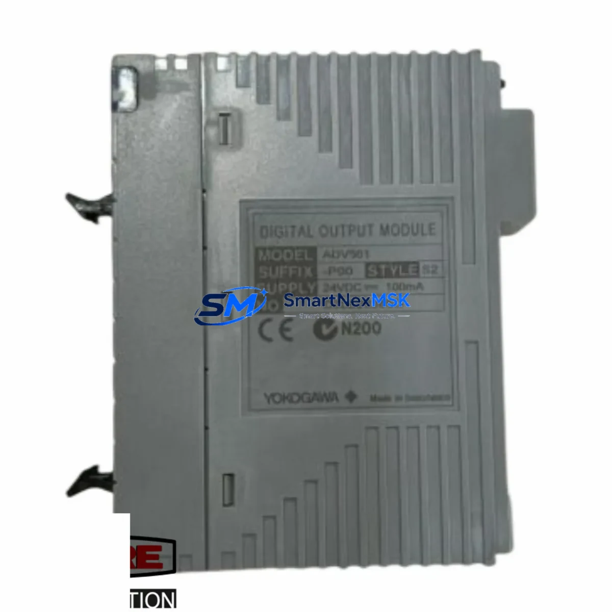
YOKOGAWA ADV561-P00 S2 Retrofit-Ready Digital Output Module for CENTUM VP & CS 3000 Control Systems
The YOKOGAWA ADV561-P00 S2 is a 16-point digital output (DO) module engineered for seamless integration into CENTUM VP and CS 3000 distributed control system (DCS) architectures. Designed as a direct retrofit replacement for aging or discontinued DO modules within the same product family, the ADV561-P00 S2 enables plant engineers and system integrators to modernize legacy control cabinets without redesigning field wiring, modifying backplane configurations, or rewriting existing control logic. Whether you are managing a planned upgrade cycle or responding to an unplanned module failure, this module delivers the compatibility, reliability, and supply continuity that industrial operations demand.
Upgrade Compatibility Table
| Parameter | ADV561-P00 S2 Specification | Retrofit Notes |
|---|---|---|
| Output Points | 16-point digital output | Direct replacement for same-slot DO modules in CENTUM VP / CS 3000 |
| Communication Protocol | V-net (YOKOGAWA proprietary fieldbus) | No protocol migration required; plug-and-play on existing V-net backbone |
| Backplane Interface | Standard CENTUM VP / CS 3000 node unit backplane | Verify node unit slot assignment before installation; no backplane modification needed |
| Power Supply Compatibility | Powered via node unit bus (24 VDC field side) | Confirm field power capacity on existing PWR48-P10 or equivalent power supply module |
| Terminal Wiring | Compatible with standard CENTUM terminal assembly | Existing field cable terminations can be retained; no rewiring required |
| Module Address | Configured via CENTUM VP Engineering Environment (CAMS for HIS) | Restore module address from backup; verify IOM tag assignments in FCS builder |
| Program Compatibility | Fully compatible with existing FCS function block logic | No control logic rewrite required; validate DO channel assignments post-swap |
| HMI Integration | Recognized by CENTUM VP HIS without graphic modification | Confirm alarm faceplates and trend tags remain mapped after module replacement |
| Installation Format | Hot-swap capable (with proper FCS shutdown procedure) | Follow YOKOGAWA module replacement SOP to minimize process interruption |
| Warranty | 12-Month Warranty | Covered from date of shipment; includes functional verification and burn-in test |
Retrofit Planning for Existing Automation Systems
Successful integration of the ADV561-P00 S2 into an operating plant begins well before the module arrives on site. A structured retrofit plan should account for the full scope of the control node — not just the DO module being replaced. In a typical CENTUM VP node unit, the ADV561-P00 S2 shares a backplane with other I/O modules such as the AAI141-S00 analog input module, the ADV151-P00 digital input module, and the AAV542-S00 analog output module. Each of these modules draws power from the shared node bus, so the first step is to audit the PWR48-P10 power supply module capacity and confirm that adding or replacing the ADV561-P00 S2 does not exceed the rated load.
Next, review the node unit’s ESB bus or V-net segment topology. In multi-node configurations, the ESB-Bus coupler or the RIO (Remote I/O) node controller — such as the ANB10D or ANR10D — governs communication between the field station and the FCS (Field Control Station). Confirm that the node address and slot number assigned to the ADV561-P00 S2 in the CENTUM VP engineering database match the physical installation. Mismatched addresses are the most common cause of post-replacement communication faults and can be resolved quickly using the CENTUM VP System View diagnostic tool.
For plants still operating on CS 3000 hardware, the ADV561-P00 S2 is a validated replacement for equivalent CS 3000 DO modules. The migration path from CS 3000 to CENTUM VP often involves retaining existing field wiring and terminal assemblies while upgrading the FCS, HIS workstations, and communication infrastructure. In this scenario, the ADV561-P00 S2 bridges the gap — it can be installed in a CENTUM VP node unit that replaces a CS 3000 node, preserving the original field cable schedule and reducing the engineering effort required for I/O re-termination.
Where the control system includes HART-enabled field devices, verify whether the existing DO channels require HART pass-through capability. If HART communication is needed for smart valve positioners or solenoid diagnostics, consult the YOKOGAWA HART multiplexer or the AAI841-S00 HART-enabled analog module as a companion device. Programming cables such as the KS1-USB or the CENTUM VP engineering laptop with CAMS for HIS software are required for module commissioning and tag verification after installation.
Downtime Control During System Migration
Minimizing process downtime during a DO module replacement requires a disciplined sequence of pre-outage, outage, and post-outage activities. Before taking the node offline, export the current FCS builder project and create a full backup of the CENTUM VP engineering database, including all IOM definitions, function block assignments, and alarm configurations. This backup serves as the recovery baseline if the replacement module requires re-commissioning from scratch.
During the outage window, place all DO channels associated with the ADV561-P00 S2 into manual mode at the HIS operator station. This prevents spurious output signals from reaching field actuators — such as motor starters, solenoid valves, or relay panels — during the physical module swap. After installing the replacement module, power up the node unit and allow the FCS to perform its self-diagnostic cycle. The CENTUM VP System View will display the module status; a green node icon confirms successful recognition and communication on the V-net segment.
Post-replacement verification should include a channel-by-channel output test using the CENTUM VP test function, confirming that each of the 16 DO points drives the correct field device. Cross-reference the as-built wiring schedule against the IOM tag list to catch any terminal transpositions introduced during the swap. Once all channels are verified, return the FCS to automatic mode and monitor the first 30 minutes of operation for any unexpected alarms or communication timeouts. This structured approach consistently achieves module replacements within a 2–4 hour planned maintenance window, even in complex multi-node DCS architectures.
Retrofit Support FAQ
Q1: Is the ADV561-P00 S2 a direct drop-in replacement for older CENTUM VP and CS 3000 digital output modules?
Yes. The ADV561-P00 S2 is designed as a form-fit-function replacement for compatible DO modules within the CENTUM VP and CS 3000 product families. It uses the same backplane connector, V-net communication protocol, and terminal assembly interface, allowing installation without field wiring changes. Always verify the slot assignment and module address in the CENTUM VP engineering environment before powering up.
Q2: What commissioning steps are required after installing the ADV561-P00 S2?
After physical installation, use the CENTUM VP System View to confirm the module is recognized on the V-net segment. Restore the IOM tag assignments from your engineering database backup, then perform a channel-by-channel output test using the CENTUM VP test function. Verify that all 16 DO points drive the correct field devices and that no alarm conditions are active before returning the FCS to automatic control mode.
Q3: Can the ADV561-P00 S2 be used in a CS 3000 to CENTUM VP migration project?
Yes. The ADV561-P00 S2 is compatible with CENTUM VP node units used in CS 3000 migration projects. When replacing a CS 3000 node with a CENTUM VP equivalent, the existing field wiring and terminal assemblies can typically be retained, and the ADV561-P00 S2 can be installed in the new node unit without re-termination. Confirm compatibility with your YOKOGAWA system integrator or refer to the CENTUM VP migration engineering guide.
Q4: What does the 12-month warranty cover, and how is the module tested before shipment?
Every ADV561-P00 S2 unit supplied by SMARTNEXMSK undergoes functional verification and burn-in testing prior to shipment. The 12-month warranty covers manufacturing defects and functional failures under normal operating conditions, commencing from the date of shipment. Warranty claims are supported by our technical team; contact [email protected] with your order reference and a description of the fault for rapid resolution.
© 2026 SMARTNEXMSK. All rights reserved.
Original Source: https://smartnexmsk.com
Contact: [email protected] | +86 18259474341



