
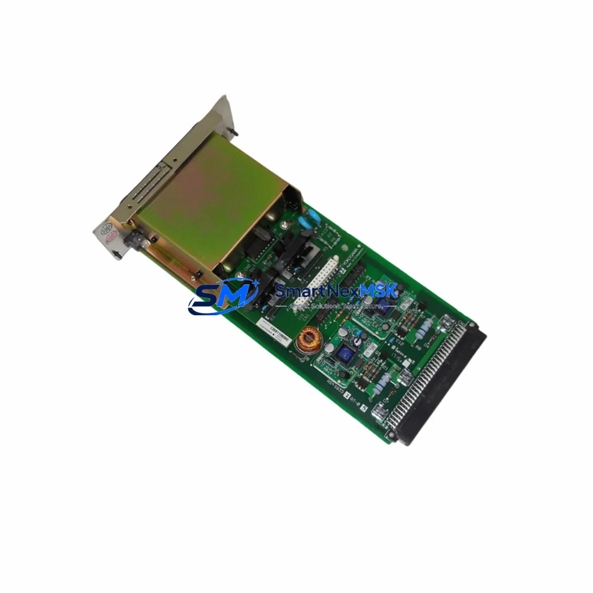
YOKOGAWA AIP434-S1 Retrofit-Ready Analog Input Module for FA-M3 Control Systems
The YOKOGAWA AIP434-S1 is a 4-channel isolated analog input module designed for the YOKOGAWA FA-M3 series programmable logic controller platform. As legacy FA-M3 installations continue to operate across process industries, petrochemical plants, power generation facilities, and discrete manufacturing lines, the AIP434-S1 has become one of the most sought-after retrofit components for engineers managing aging control infrastructure. Whether you are replacing a failed module, upgrading a control cabinet, or migrating from an earlier FA-M3 analog I/O configuration, the AIP434-S1 delivers drop-in compatibility with minimal re-engineering effort.
Each unit supplied by SMARTNEXMSK is sourced from verified industrial channels, subject to pre-shipment functional testing, and covered by a 12-month warranty. Our inventory is maintained specifically to support customers who require fast turnaround on discontinued or hard-to-source YOKOGAWA FA-M3 components, reducing unplanned downtime and keeping critical production lines operational.
Upgrade Compatibility Table
| Parameter | AIP434-S1 Specification | Retrofit Notes |
|---|---|---|
| Module Type | 4-ch Isolated Analog Input | Direct replacement for AIP434 and compatible FA-M3 analog input slots |
| Signal Range | 4–20 mA / 1–5 V (channel-selectable) | Verify field wiring signal type before installation; no hardware jumper change required for standard ranges |
| Backplane Interface | FA-M3 standard module bus | Compatible with F3SP22, F3SP28, F3SP38, F3SP53, F3SP58, F3SP67 CPU modules |
| Power Consumption | Confirm from module label (typically 5 VDC internal bus) | Verify base unit power budget; check F3BU04-0N or F3BU16-0N base capacity before adding modules |
| Terminal Wiring | Screw terminal block (field-removable) | Retain original terminal block wiring diagram; re-use existing field cables where signal type matches |
| Module Address | Slot-based addressing via FA-M3 base unit | Module address is determined by physical slot position; no DIP switch configuration required |
| Program Compatibility | FA-M3 WideBand ladder / function block | Existing YOKOGAWA WideBand programs referencing AIP434 I/O addresses are directly compatible; no program modification required for same-slot replacement |
| Communication Link | Internal FA-M3 module bus (not Ethernet/serial) | No impact on F3LE01-5T Ethernet or F3LC11-1F MELSEC link modules in the same rack |
| HMI Compatibility | YOKOGAWA ProSafe-RS / FAST/TOOLS / third-party SCADA via OPC | HMI tag addresses tied to I/O slot positions remain valid after same-slot replacement; verify tag database if slot position changes |
| Warranty | 12 Months | Covers manufacturing defects and functional failure under normal operating conditions from date of shipment |
Retrofit Planning for Existing Automation Systems
Successful integration of the AIP434-S1 into an existing FA-M3 control system begins with a thorough audit of the current rack configuration. Engineers should document the base unit model — typically an F3BU04-0N (4-slot) or F3BU16-0N (16-slot) — and confirm available power budget before inserting any replacement module. The FA-M3 platform distributes 5 VDC and 24 VDC across the backplane, and cumulative module power draw must remain within the base unit’s rated capacity.
Terminal wiring is the most time-sensitive step in any analog module replacement. The AIP434-S1 uses a field-removable screw terminal block, which allows technicians to disconnect the terminal assembly as a single unit, preserving field wiring integrity while the module is swapped. Before removal, photograph or transcribe the existing wiring layout, noting signal polarity, shield grounding points, and any 2-wire transmitter loop power connections. If the original installation used a F3YP28-0P pulse output module or F3XD32-3H digital input module in adjacent slots, confirm that their terminal blocks are not mechanically interfering with the AIP434-S1 installation.
For sites migrating from earlier YOKOGAWA Micro-XL or STARDOM FCN/FCJ controllers to the FA-M3 platform, the AIP434-S1 provides a standardized analog input interface that simplifies I/O mapping during program conversion. Engineers using YOKOGAWA’s WideBand programming environment will find that analog input function blocks referencing the AIP434-S1’s slot address can be directly mapped from legacy Micro-XL analog input tags with minimal rework. Where the original system used a YOKOGAWA AMC80 or AMC81 analog module, signal scaling parameters should be re-verified in the new program, as resolution and engineering unit conversion factors may differ.
Communication architecture should also be reviewed during retrofit planning. FA-M3 systems commonly integrate F3LE01-5T Ethernet interface modules for SCADA connectivity, F3LC11-1F MELSEC link modules for inter-PLC communication, and F3SP67-6S safety CPU modules in safety-instrumented system (SIS) applications. The AIP434-S1 operates entirely on the internal module bus and does not affect the configuration or performance of these communication modules. However, if the retrofit involves relocating the AIP434-S1 to a different slot position, all SCADA tag addresses, OPC server item paths, and HMI screen bindings that reference the original slot number must be updated accordingly.
For I/O expansion projects, the AIP434-S1 can coexist in the same base unit with YOKOGAWA F3AD04-0N additional analog input modules, F3DA04-0N analog output modules, and F3XD32-3H high-density digital input modules. When planning a multi-module upgrade, always sequence the installation to maintain at least one operational CPU scan cycle between module insertions, allowing the FA-M3 CPU to re-enumerate the rack configuration without triggering a hardware fault alarm.
Downtime Control During System Migration
Minimizing production downtime during an FA-M3 analog module replacement requires preparation that begins well before the maintenance window. The recommended approach is to pre-configure and bench-test the AIP434-S1 offline using a spare FA-M3 base unit and a YOKOGAWA F3SP22 or equivalent CPU module. Load the existing production program onto the test CPU, insert the AIP434-S1 into the target slot, and verify that the CPU recognizes the module without generating a module type mismatch error. This offline validation step eliminates the most common cause of extended downtime — discovering a configuration incompatibility only after the production system has been shut down.
During the live replacement, use the FA-M3 CPU’s online monitoring function to capture the last known analog input values before shutdown. Record these values as reference points for post-installation verification. After inserting the AIP434-S1 and restoring power, confirm that each channel’s live reading matches the expected process value within the instrument’s calibrated range. If readings deviate, check terminal wiring polarity and confirm that the field transmitter’s loop power supply — often sourced from a dedicated 24 VDC panel supply rather than the module itself — is active and within specification.
For systems where continuous process monitoring is critical, consider implementing a temporary bypass using a portable data logger connected in parallel with the existing field transmitters before the module swap. This preserves process visibility during the brief period when the FA-M3 analog input channels are offline. Once the AIP434-S1 is confirmed operational, the bypass can be removed without interrupting the process. The entire hot-swap procedure, from module removal to verified online operation, typically requires 15 to 30 minutes for a single-module replacement when the pre-installation preparation steps have been completed.
Program logic integrity is preserved automatically when the AIP434-S1 replaces a module of the same type in the same slot, as the FA-M3 CPU does not require a program download after a same-type module replacement. If the CPU is in RUN mode during the swap, it will briefly enter a module error state and then resume normal operation once the new module is recognized. For safety-critical applications, coordinate the replacement with the site’s management of change (MOC) procedure and confirm with the control system engineer that the brief input interruption will not trigger a process interlock or emergency shutdown sequence.
Retrofit Support FAQ
Q1: Is the AIP434-S1 a direct drop-in replacement for the original AIP434 module?
Yes. The AIP434-S1 is the current production variant of the AIP434 analog input module for the YOKOGAWA FA-M3 series. It occupies the same physical slot, uses the same backplane connector, and is recognized by the FA-M3 CPU under the same module type identifier. No program modification is required when replacing an AIP434 with an AIP434-S1 in the same slot position.
Q2: What commissioning steps are required after installation?
After physical installation, power up the FA-M3 base unit and confirm that the CPU’s module status display shows the AIP434-S1 as recognized without error. Verify each analog input channel by comparing the live reading in the WideBand monitoring screen against a calibrated reference signal or the known process value. If channel scaling was customized in the original program, confirm that the engineering unit conversion parameters in the function block remain unchanged. No additional hardware calibration is required for standard 4–20 mA or 1–5 V signal ranges.
Q3: Can the AIP434-S1 be used in FA-M3 systems with mixed CPU generations?
Yes. The AIP434-S1 is compatible with all FA-M3 CPU modules that support the standard analog input module type, including F3SP22, F3SP28, F3SP38, F3SP53, F3SP58, and F3SP67 series CPUs. It can coexist in the same base unit with both older and newer FA-M3 I/O modules without compatibility issues.
Q4: What does the 12-month warranty cover, and what is the process for a warranty claim?
The 12-month warranty covers manufacturing defects and functional failure under normal operating conditions, commencing from the date of shipment. Each unit undergoes pre-shipment functional testing before dispatch. To initiate a warranty claim, contact SMARTNEXMSK at [email protected] with your order reference, a description of the fault, and photographic evidence of the module and installation environment. Replacement or repair will be arranged within the warranty period at no additional cost to the customer.
© 2026 SMARTNEXMSK. All rights reserved.
Original Source: https://smartnexmsk.com
Contact: [email protected] | +86 18259474341



