
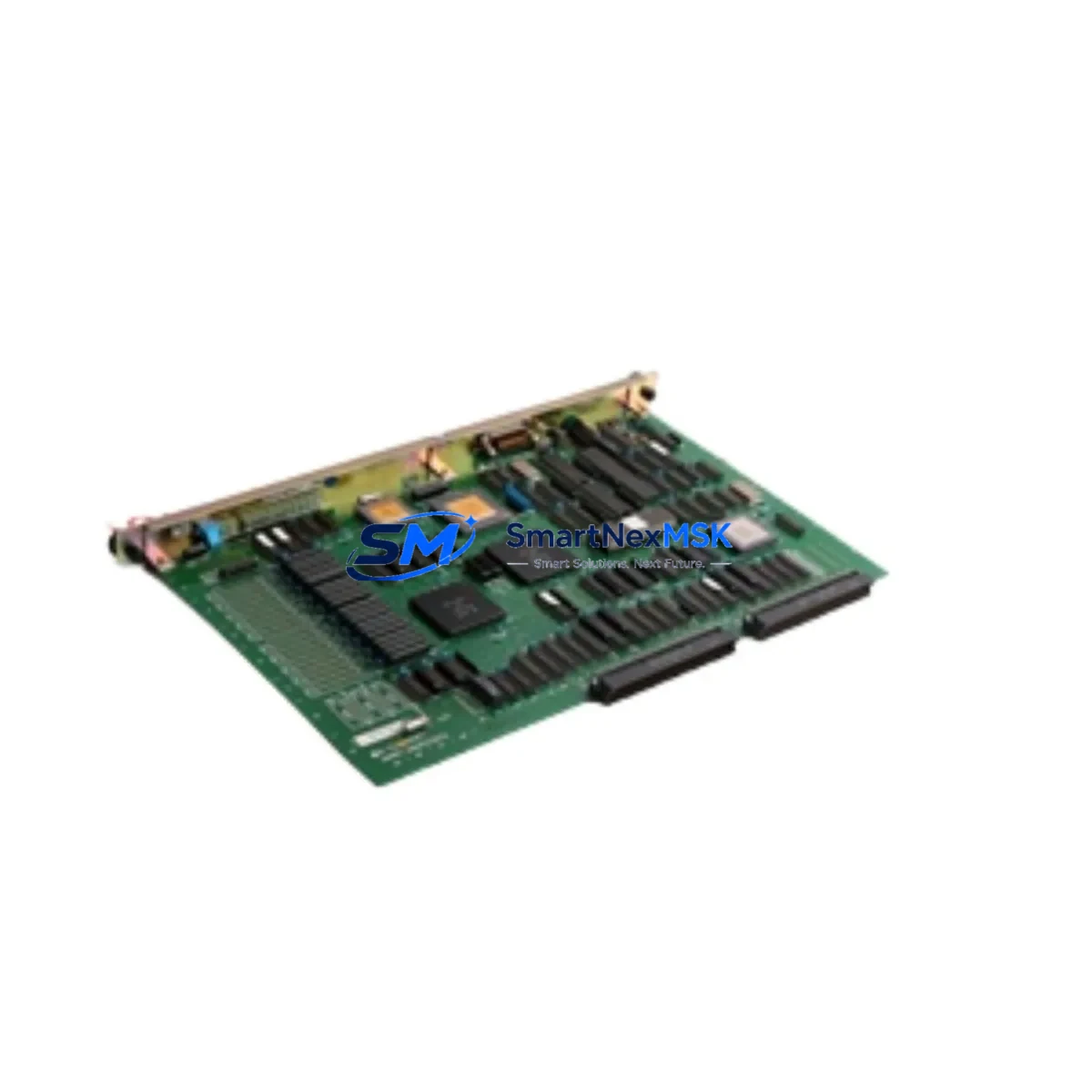
YOKOGAWA CP99A*A S9581AS-0 Retrofit-Ready FCS CPU for CENTUM CS 3000 Control Systems
The YOKOGAWA CP99A*A S9581AS-0 is a Field Control Station (FCS) CPU card engineered for the CENTUM CS 3000 Distributed Control System platform. As legacy CENTUM CS 3000 installations approach end-of-life and original spare parts become increasingly scarce, this module serves as a critical retrofit and replacement component for facilities seeking to extend operational life, reduce unplanned downtime, and maintain process continuity without committing to a full DCS migration.
Whether you are replacing a failed processor card in an active control loop, upgrading a degraded FCS node, or building a cold-standby inventory for a critical production line, the CP99A*A S9581AS-0 provides the processing architecture, backplane compatibility, and firmware baseline required for seamless integration into existing CENTUM CS 3000 cabinets. Each unit is functionally tested prior to shipment and backed by a 12-month warranty covering hardware defects under normal operating conditions.
Upgrade Compatibility Table
| Parameter | Details |
|---|---|
| Compatible Platform | YOKOGAWA CENTUM CS 3000 DCS |
| Module Type | FCS CPU Card (Field Control Station Processor) |
| SKU / Part Number | CP99A*A S9581AS-0 |
| Backplane Interface | CENTUM CS 3000 standard FCS backplane slot |
| Installation Requirement | Direct slot replacement; no mechanical modification required |
| Communication Compatibility | Vnet (V-net) control bus; compatible with existing Vnet topology |
| Firmware / Software | Compatible with CENTUM CS 3000 R3.xx engineering environment |
| Replacement Recommendation | Suitable for direct swap of failed or degraded CP99A-series FCS CPU cards |
| Commissioning Notes | Module address assignment and FCS domain configuration required post-installation; verify via System View |
| Warranty | 12-Month Hardware Warranty — covers manufacturing defects under normal use |
| Pre-Shipment Testing | Full functional test performed on each unit before dispatch |
| Origin | Japan |
Retrofit Planning for Existing Automation Systems
Successful integration of the CP99A*A S9581AS-0 into an operating CENTUM CS 3000 system requires careful pre-installation planning across several subsystems. Before removing the existing FCS CPU card, engineers should verify that the FCS power supply module — typically an PW481 or equivalent CENTUM CS 3000 power unit — is delivering stable DC voltage within specification, as an undersized or aging power supply is a common root cause of repeated CPU card failures.
The FCS node’s backplane and I/O nest should be inspected for corrosion, bent connector pins, or accumulated contamination that could cause intermittent contact faults after the new card is seated. Terminal wiring connected to associated I/O modules — including AI (Analog Input), AO (Analog Output), DI (Digital Input), and DO (Digital Output) cards installed in the same FCS nest — should be documented and verified against the original loop drawings before any card swap is attempted.
For sites running redundant FCS configurations, the CP99A*A S9581AS-0 supports hot-standby pairing when installed alongside a matching primary FCS CPU. The Vnet communication link between the FCS and the HIS (Human Interface Station) operator consoles must remain active during the swap procedure to preserve real-time process visibility. Engineers should confirm that the ER bus (Engineering Router) connection to the FCS domain is stable and that the CENTUM CS 3000 System View software on the engineering workstation can detect the new module after insertion.
In systems where the FCS communicates with field devices via FOUNDATION Fieldbus H1 or HART protocol through an FCU (Field Communication Unit) or ALF111 fieldbus coupler, the communication link parameters should be re-verified after the CPU card replacement to ensure that device descriptors and function block schedules are correctly loaded. Similarly, if the FCS interfaces with a safety instrumented system via a dedicated SIS gateway or ProSafe-RS safety controller, the inter-system communication watchdog timers should be checked post-commissioning.
Sites planning a broader CENTUM CS 3000 upgrade — such as migrating from CS 3000 to CENTUM VP — may use the CP99A*A S9581AS-0 as an interim stabilization measure, keeping the existing FCS infrastructure operational while the migration project is scoped and budgeted. In this context, the module also pairs naturally with CP345 controller cards, EB401 Vnet/IP interface modules, and RIO (Remote I/O) node components that remain in service during a phased migration.
Downtime Control During System Migration
Minimizing control system downtime during an FCS CPU card replacement is the primary operational concern for process facilities running continuous production. The recommended approach is to perform the swap during a scheduled maintenance window, with the process placed in manual control mode at the field level — using local control stations or manual loading stations — before the FCS is taken offline.
Prior to removal of the existing CP99A-series card, a full backup of the FCS control database should be exported from the CENTUM CS 3000 engineering environment, including all function block parameters, tuning constants, alarm setpoints, and interlock logic. This backup serves as the restoration baseline if the new module requires a full database download rather than a hot-swap recognition.
In redundant FCS configurations, the switchover to the standby CPU can be initiated from System View before the primary card is removed, allowing the process to continue running on the standby node while the primary slot is serviced. This approach reduces effective process downtime to near zero for redundant installations. For simplex (non-redundant) FCS nodes, the total downtime window is typically limited to the time required for physical card swap, module address verification, database download confirmation, and Vnet communication re-establishment — a process that experienced CENTUM CS 3000 engineers can complete in under 30 minutes under favorable conditions.
After the new CP99A*A S9581AS-0 is installed and the FCS is brought back online, a systematic loop check should be performed across all I/O channels in the affected FCS nest, confirming that analog signal ranges, digital contact states, and PID controller outputs match pre-shutdown values before returning the process to automatic control. HMI faceplate displays on the HIS operator stations should be verified to confirm that all associated control loops are displaying correctly and that no spurious alarms have been generated by the restart sequence.
Retrofit Support FAQ
Q1: Is the CP99A*A S9581AS-0 a direct drop-in replacement for other CP99A-series FCS CPU cards in CENTUM CS 3000?
A: Yes. The CP99A*A S9581AS-0 is designed for direct slot replacement within the CENTUM CS 3000 FCS backplane. It is compatible with standard CP99A-series installations. Module address and domain configuration should be verified in System View after installation to confirm correct FCS node recognition.
Q2: What commissioning steps are required after installing the replacement card?
A: After physical installation, engineers should confirm module address assignment via the FCS rotary switches, verify Vnet communication link status in System View, download or confirm the FCS control database, and perform a channel-by-channel I/O loop check. For redundant FCS pairs, the standby synchronization status should also be confirmed before returning to automatic control.
Q3: How is terminal wiring and backplane compatibility verified before installation?
A: Terminal wiring connected to I/O modules in the same FCS nest should be verified against original loop drawings. The backplane connector should be inspected for physical damage. Power supply output voltage should be measured at the FCS power terminals to confirm it is within the specified range for the CP99A*A module before the card is seated.
Q4: What does the 12-month warranty cover, and how is it supported?
A: The 12-month warranty covers hardware manufacturing defects under normal operating conditions. Each unit undergoes functional testing prior to shipment. Warranty claims are supported via direct contact with our technical team. Damage resulting from incorrect installation, overvoltage, or environmental factors outside the module’s rated operating range is not covered under the standard warranty terms.
© 2026 SMARTNEXMSK. All rights reserved.
Original Source: https://smartnexmsk.com
Contact: [email protected] | +86 18259474341



