
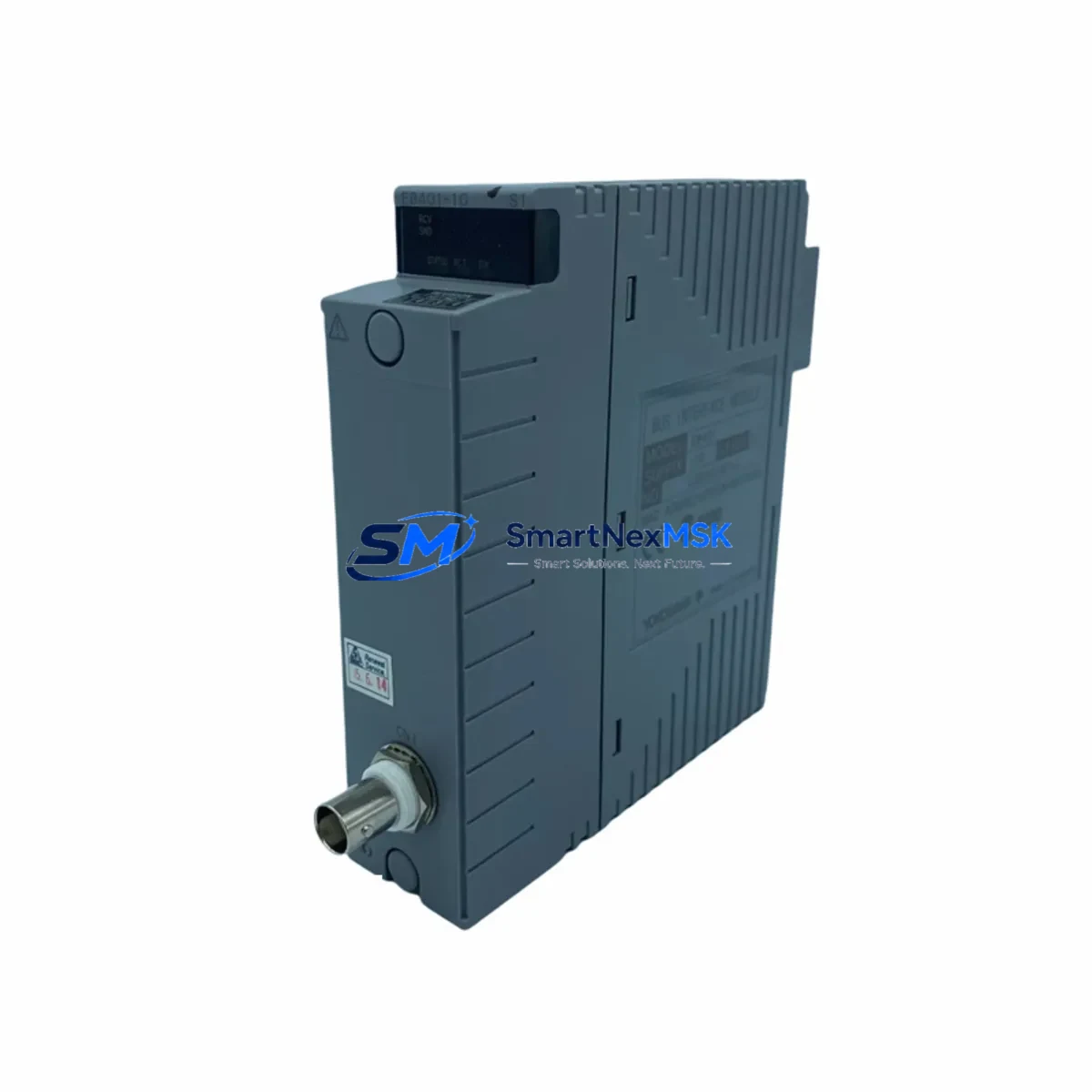
Yokogawa EB401-10 Retrofit-Ready ER Bus Interface Module: Compatible Modernization for CENTUM VP Control Systems
The Yokogawa EB401-10 is a field-proven ER Bus interface module designed for integration within the CENTUM VP distributed control system platform. As legacy CENTUM CS 3000 and early CENTUM VP installations approach end-of-life, the EB401-10 has become a critical retrofit component for engineers managing control cabinet upgrades, I/O expansion projects, and bus communication migrations. Whether you are replacing a discontinued module, restoring a failed node, or modernizing an aging production line, the EB401-10 provides a reliable, wiring-compatible solution that minimizes engineering rework and reduces total downtime.
This module serves as the backbone of ER Bus communication within the CENTUM VP field control station architecture. It interfaces directly with the FCS (Field Control Station) backplane, enabling seamless data exchange between I/O modules and the control network. Engineers replacing older EB401 variants or migrating from CENTUM CS 3000 bus structures will find the EB401-10 fully compatible with existing terminal wiring, module addressing schemes, and HMI tag configurations — eliminating the need for costly reprogramming or panel rewiring.
Upgrade Compatibility Table
| Parameter | Details |
|---|---|
| SKU / Part Number | EB401-10 |
| Brand | Yokogawa |
| Series | CENTUM VP / CENTUM CS 3000 |
| Module Function | ER Bus Interface Module |
| Bus Protocol | ER Bus (Enhanced Remote Bus) |
| Backplane Interface | Compatible with CENTUM VP FCS backplane slots |
| Installation Type | DIN rail / rack-mount within FCS cabinet |
| Wiring Compatibility | Drop-in replacement; existing terminal wiring retained |
| Module Address | Configurable via hardware DIP switch or engineering tool |
| Communication Compatibility | ER Bus, compatible with Vnet/IP upstream network |
| Replacement Recommendation | Direct replacement for EB401, EB401-1, EB401-10 legacy units |
| Commissioning Notes | Verify FCS node address, I/O map, and HMI tag binding post-swap |
| Power Supply Requirement | Supplied via FCS backplane; verify PSU capacity before installation |
| Origin | Japan |
| Warranty | 12-Month Warranty — functional test report available on request |
Retrofit Planning for Existing Automation Systems
Successful EB401-10 retrofits begin with a thorough audit of the existing FCS cabinet. Before removing the failed or obsolete module, engineers should document the current module slot address, verify the power supply unit (PSU) — typically a Yokogawa PW481 or PW482 — has sufficient capacity to support the replacement module, and photograph all terminal wiring for reference during reinstallation.
The EB401-10 connects to the ER Bus segment that links remote I/O nodes back to the FCS. In systems where the ER Bus carries signals from AAI141 analog input modules, AAI841 analog output modules, or ADV151 digital input modules, the bus interface must be restored before any I/O data can be read or written by the controller. Engineers should also confirm that the ACF11 or ACF12 communication coupler modules on the same bus segment are functioning correctly, as a faulty coupler can cause the EB401-10 to appear defective during initial power-up.
For sites running CENTUM VP R5 or later, the Field Communicator or CENTUM VP Engineering Environment (ENG) software is used to re-register the module after physical replacement. The module address must match the original FCS configuration file exactly — any mismatch will prevent the FCS from recognizing the new module and will generate a hardware fault alarm on the HIS (Human Interface Station). If the original project files are unavailable, the address can be read from the surviving modules on the same ER Bus segment using the engineering tool’s online hardware scan function.
In multi-cabinet installations, the ER Bus may span across junction boxes using EB501 bus extender modules. Confirm that all bus termination resistors are correctly installed at both ends of the ER Bus segment before powering up the replacement EB401-10. Incorrect termination is a common cause of intermittent communication errors that are difficult to diagnose after the module swap is complete.
For projects involving a broader migration from CENTUM CS 3000 to CENTUM VP, the EB401-10 is often installed alongside new FCS (Field Control Station) units and Vnet/IP network switches. In these scenarios, the ER Bus I/O nodes are retained and reconnected to the new FCS via the EB401-10, preserving the existing field wiring investment while the control logic is migrated to the new platform. Programming cables such as the KS1-USB are used during commissioning to verify module communication and download updated FCS configuration files.
Downtime Control During System Migration
Minimizing production downtime during an EB401-10 replacement requires careful pre-staging and a structured hot-swap procedure. Before the maintenance window begins, the replacement module should be pre-configured with the correct bus address and verified against the original hardware settings using the engineering workstation. All I/O signals connected to the affected ER Bus segment should be identified, and operators should be briefed on which control loops will be temporarily unavailable during the swap.
Where the process permits, place affected control loops in manual mode at the HIS before disconnecting the failed module. This protects the original PID logic and prevents the FCS from issuing spurious output commands when the bus is interrupted. After the EB401-10 is seated and the bus is restored, bring each loop back to automatic mode one at a time, verifying process values against field instruments before releasing control.
For critical processes where even brief interruptions are unacceptable, a redundant FCS configuration with a standby ER Bus path can be used to maintain control continuity during the swap. In this configuration, the standby FCS takes over control while the primary bus interface is replaced, and control is transferred back after the new EB401-10 has been verified online. This approach requires that the redundant FCS and its associated ER Bus segment are fully operational before the maintenance window begins.
All replacement modules supplied by SMARTNEXMSK are functionally tested prior to shipment. A test report confirming bus communication, module self-diagnostics, and power-up behavior is available on request. This pre-shipment verification significantly reduces the risk of receiving a non-functional module and allows engineers to proceed with confidence during the maintenance window.
Retrofit Support FAQ
Q1: Is the EB401-10 a direct drop-in replacement for the original EB401 and EB401-1 modules?
Yes. The EB401-10 is backward compatible with earlier EB401 variants and uses the same backplane connector, module address scheme, and ER Bus protocol. No changes to terminal wiring or FCS configuration files are required in most standard replacement scenarios. Confirm the hardware revision of your FCS backplane before installation if you are working with very early CENTUM CS 3000 hardware.
Q2: What commissioning steps are required after installing the EB401-10?
After physical installation, use the CENTUM VP Engineering Environment to perform an online hardware scan and confirm the module is recognized at the correct slot address. Verify that all I/O channels on the connected ER Bus segment are reporting correctly at the HIS. Check for any hardware fault alarms and clear them after confirming the module is online. Finally, restore any control loops that were placed in manual mode during the swap.
Q3: How do I verify wiring compatibility before removing the old module?
Document all terminal connections on the existing module using the FCS wiring diagram or as-built drawings. The EB401-10 uses the same terminal layout as its predecessors, so existing field cables can be reconnected without modification. If as-built drawings are unavailable, photograph the terminal block before disconnecting any wires and use the engineering tool to export the current I/O assignment list for reference.
Q4: What warranty and testing does SMARTNEXMSK provide with the EB401-10?
All EB401-10 modules supplied by SMARTNEXMSK carry a 12-month warranty covering functional defects under normal operating conditions. Each unit undergoes a pre-shipment functional test including bus communication verification, power-up self-diagnostics, and module address confirmation. A test report is available on request. In the event of a warranty claim, SMARTNEXMSK provides a replacement unit and technical support to assist with reinstallation and recommissioning.
© 2026 SMARTNEXMSK. All rights reserved.
Original Source: https://smartnexmsk.com
Contact: [email protected] | +86 18259474341



