
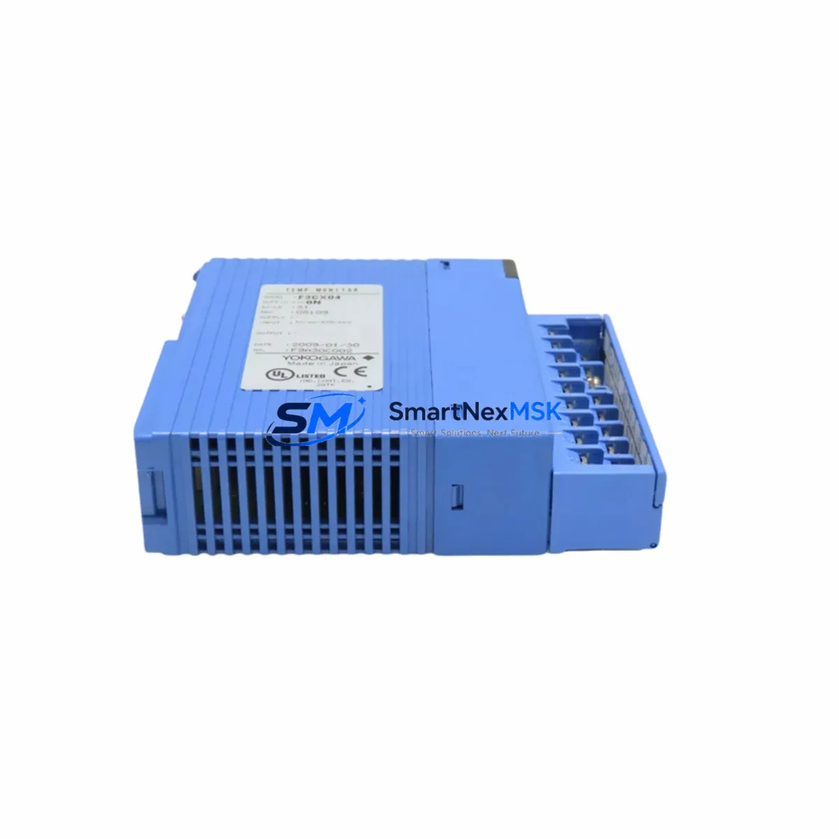
YOKOGAWA F3AD04-0N Retrofit-Ready Analog Input Module for FA-M3 Control Systems
The YOKOGAWA F3AD04-0N is a 4-channel analog input module designed for the FA-M3 series programmable controller platform. As legacy FA-M3 installations age and original spare parts become increasingly scarce, the F3AD04-0N has become a critical retrofit component for engineers managing aging control cabinets across process industries including petrochemical, power generation, water treatment, and discrete manufacturing. This module accepts standard 4–20 mA and 1–5 V DC signals, making it directly compatible with field transmitters already wired into existing control loops without requiring signal conditioning changes.
When sourcing the F3AD04-0N as a replacement for a failed or end-of-life unit, engineers must verify several key parameters before installation. The module occupies a single slot on the FA-M3 base unit or expansion rack, and the slot address must be confirmed against the existing I/O assignment table in the ladder program. Incorrect slot addressing will cause the CPU — typically an F3SP22-0S, F3SP28-3N, or F3SP38-6N — to generate a hardware fault and halt scan execution. Always cross-reference the I/O map in the WIDE Field Network programming tool before powering the rack.
Upgrade Compatibility Table
| Parameter | F3AD04-0N Specification | Retrofit Notes |
|---|---|---|
| Input Channels | 4 channels (analog) | Verify channel count matches existing wiring schedule |
| Input Signal Range | 4–20 mA / 1–5 V DC | Confirm field transmitter output type before installation |
| Rack Compatibility | FA-M3 base unit & expansion racks | Compatible with F3BU04-0N, F3BU08-0N, F3BU16-0N base units |
| Slot Addressing | Automatic via backplane | Confirm slot number in I/O assignment table; no DIP switch required |
| Power Consumption | Supplied via backplane (5 VDC) | Verify power supply module (e.g. F3PU20-0S) has sufficient margin |
| Communication Protocol | FA-M3 internal backplane bus | No external protocol configuration required |
| Programming Tool | WIDE Field Network / ToolBox | Existing ladder logic is retained; no program rewrite needed |
| HMI Compatibility | Compatible with existing FA-M3 HMI tag addresses | Verify register addresses in HMI (e.g. YOKOGAWA ProSafe-RS or third-party SCADA) |
| Replacement Scope | Direct drop-in for same-slot F3AD04-0N units | No mechanical modification required |
| Warranty | 12-Month Warranty | Covers manufacturing defects; includes pre-shipment functional test |
Retrofit Planning for Existing Automation Systems
A successful F3AD04-0N retrofit begins with a thorough audit of the existing control cabinet. Start by documenting the current rack layout — identifying the base unit model (such as the F3BU08-0N or F3BU16-0N), the position of the power supply module (commonly the F3PU20-0S or F3PU10-0S), and the slot assignments of all installed I/O modules. The F3AD04-0N draws its operating power from the backplane, so the total current budget of the power supply must be recalculated when adding or replacing modules, particularly if the cabinet has been expanded since original commissioning.
Terminal wiring for the F3AD04-0N uses a removable screw-terminal connector block. Before removing the failed module, photograph or document the existing field wiring connections — channel polarity, shield grounding, and cable routing — to ensure accurate reconnection. In many legacy installations, field cables are labeled inconsistently, and a wiring audit at this stage prevents signal inversion errors that are difficult to diagnose after the panel is closed.
For systems that also require communication module upgrades, the FA-M3 platform supports a range of network options. If the existing installation uses a F3LE01-5T Ethernet module or an F3LC11-1F MELSEC I/O link module for upstream SCADA connectivity, these modules are unaffected by replacing an analog input module in a separate slot. However, if the retrofit scope includes migrating from a legacy serial link (such as RS-232C or RS-485 via an F3LC01-1N communication module) to Ethernet-based Modbus TCP or PROFINET, additional configuration steps are required in both the CPU program and the HMI tag database.
I/O expansion is another common driver for F3AD04-0N procurement. When a production line adds new measurement points — additional flow transmitters, pressure sensors, or temperature loops — engineers often need to populate previously empty slots in an existing FA-M3 rack rather than installing a new rack. In this scenario, the F3AD04-0N can be inserted into any available slot, and the I/O assignment table in the WIDE programming environment is updated to reflect the new channel addresses. The CPU (e.g. F3SP59-4S or F3SP67-6S) will automatically recognize the new module on the next power cycle without requiring a full program download.
Pre-shipment testing is performed on every F3AD04-0N unit before dispatch. Each module is powered on a live FA-M3 test rack, all four analog input channels are verified against calibrated signal sources, and the module’s diagnostic LEDs are confirmed to indicate normal operation. A test report is available upon request. All units are shipped with a 12-month warranty covering manufacturing defects and functional failures under normal operating conditions.
Downtime Control During System Migration
Minimizing unplanned downtime is the primary concern for any control system retrofit. For the F3AD04-0N replacement, the recommended approach is a hot-swap procedure during a scheduled maintenance window rather than an emergency replacement under production pressure. Before the maintenance window, prepare the replacement module, verify the slot address, and back up the current CPU program using the WIDE Field Network tool or ToolBox software to a local engineering workstation.
During the swap, the FA-M3 CPU should be placed in STOP mode to prevent spurious output commands while the analog input module is removed and reinserted. Once the F3AD04-0N is seated and the terminal block is reconnected, the CPU can be returned to RUN mode. The analog input channels will resume normal scan within one CPU scan cycle — typically less than 10 milliseconds for standard FA-M3 configurations. If the system uses a redundant CPU configuration (such as paired F3SP38-6N units in a hot-standby arrangement), the switchover to the standby CPU can be used to perform the module replacement with zero process interruption.
For systems where the F3AD04-0N feeds critical control loops — such as PID controllers managing temperature or pressure — it is advisable to place those loops in manual mode at the DCS or SCADA level before initiating the swap. This prevents the control output from driving actuators to unsafe positions during the brief period when analog feedback is unavailable. Once the replacement module is confirmed operational and channel readings are verified against field instruments, the loops can be returned to automatic control. The entire procedure, from STOP to RUN with verified signal integrity, typically takes 15 to 30 minutes for a single-module replacement.
Retrofit Support FAQ
Q: Is the F3AD04-0N a direct drop-in replacement for an existing failed unit in the same slot?
A: Yes. The F3AD04-0N is a direct slot-for-slot replacement within the FA-M3 rack. No mechanical modification, DIP switch reconfiguration, or program rewrite is required, provided the replacement unit is the same model. The CPU will recognize the module automatically on power-up or after a RUN command.
Q: What wiring checks should be performed before installing the replacement module?
A: Verify that the removable terminal block connector is correctly wired — confirm channel polarity (+ and − for each 4–20 mA loop), shield grounding at the panel end only, and that no field wires are loose or corroded. Compare against the original wiring diagram or the as-built documentation for the cabinet. Incorrect polarity on a current input channel will result in a zero or negative reading rather than a fault alarm.
Q: How is compatibility with the existing HMI and SCADA system verified after replacement?
A: After the module is installed and the CPU is in RUN mode, navigate to the analog input register addresses in the HMI (whether a YOKOGAWA-native display or a third-party SCADA system connected via Modbus or OPC-DA). Confirm that live process values are updating correctly and match the readings on local field indicators. If register values appear frozen or show maximum-scale readings, recheck the slot address assignment in the I/O table and confirm the terminal block is fully seated.
Q: What does the 12-month warranty cover, and is a pre-shipment test report available?
A: The 12-month warranty covers manufacturing defects and functional failures under normal industrial operating conditions. It does not cover damage from incorrect installation, overvoltage, or physical impact. A pre-shipment functional test is performed on every unit using a live FA-M3 test rack, and a test report confirming channel-by-channel verification can be provided upon request at the time of order.
© 2026 SMARTNEXMSK. All rights reserved.
Original Source: https://smartnexmsk.com
Contact: [email protected] | +86 18259474341



