
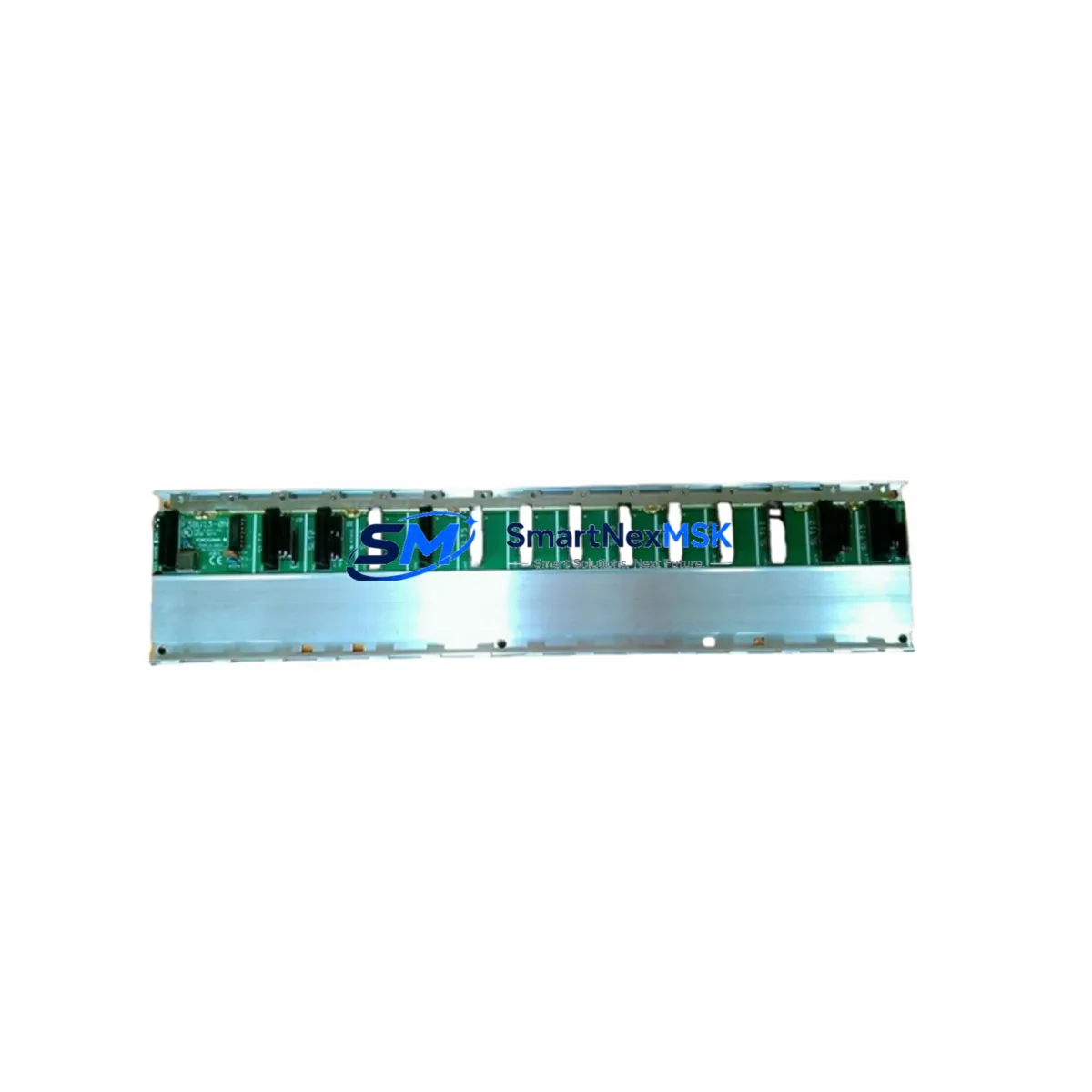
YOKOGAWA F3BU13-0N Maintenance-Ready Spare for STARDOM Automation
The YOKOGAWA F3BU13-0N is a 13-slot DCS backplane base unit engineered for the STARDOM FCN and FCN-RTU distributed control platform. In industrial facilities where continuous process control is non-negotiable, an unplanned failure of the base unit can cascade into full controller downtime — halting production, triggering safety shutdowns, and generating costly recovery cycles. Stocking a verified original spare of the F3BU13-0N is one of the most effective strategies a maintenance team can adopt to protect system uptime and reduce mean time to repair (MTTR).
This unit is sourced as an original YOKOGAWA component, fully tested prior to dispatch, and backed by a 12-month warranty. It is compatible with the STARDOM FCN controller family and supports the standard FCN module lineup, making it a direct drop-in replacement for aging or failed backplane assemblies in both greenfield and legacy installations.
Spare Maintenance Table
| Parameter | Specification / Detail |
|---|---|
| Part Number | F3BU13-0N |
| Brand | YOKOGAWA |
| Series | STARDOM FCN / FCN-RTU |
| Module Slots | 13 slots |
| Unit Type | DCS Backplane Base Unit |
| Compatibility | YOKOGAWA STARDOM FCN, FCN-RTU controller modules |
| Origin | Japan (Original OEM) |
| Installation | DIN rail / panel mount, standard FCN rack form factor |
| Operating Temperature | 0°C to 55°C (standard industrial environment) |
| Application Environment | Process automation, oil & gas, power generation, water treatment, chemical plants |
| Maintenance Recommendation | Inspect backplane connectors and bus integrity annually; replace on first sign of intermittent module communication faults |
| Condition | Original spare, pre-shipment tested |
| Warranty | 12 Months |
| Lead Time | In stock — ships within 1–3 business days |
Maintenance Planning for Continuous Operation
When a maintenance or procurement engineer evaluates the F3BU13-0N for replacement, the backplane is rarely the only component that warrants attention. A thorough site inspection and spare parts review should encompass the full FCN controller assembly and its associated electrical infrastructure.
Begin with the FCN CPU module — typically the F3SP71-4N or F3SP76-7S — which seats directly into the backplane and is the first component to exhibit communication errors when backplane bus integrity degrades. Alongside the CPU, the power supply module (such as the F3PU20-0S or F3PU10-0S) should be inspected for output voltage stability, capacitor aging, and connector wear, as power irregularities are a leading cause of premature backplane failure.
I/O modules installed in the remaining slots — including digital input modules like the F3DI32-0N, digital output modules such as the F3DO32-0N, and analog input cards in the F3AD series — should be individually reseated and tested during any backplane replacement event. Loose or oxidized module connectors can cause intermittent faults that are frequently misdiagnosed as CPU or network issues.
Communication modules, including PROFIBUS-DP interface cards and Ethernet communication modules used for SCADA or DCS integration, should also be verified for firmware version compatibility with the replacement backplane. Signal isolators and surge protection devices installed upstream of analog I/O channels are often overlooked during backplane maintenance but are critical for protecting the new unit from field-side transients.
Terminal blocks and field wiring connected to I/O modules should be inspected for insulation integrity and torque compliance. In older installations, corroded terminal strips or undersized conductors can introduce ground loops that stress the backplane bus. Finally, if the FCN controller interfaces with an HMI panel or operator workstation via serial or Ethernet, verify that the communication link is re-established and stable after the backplane swap before returning the system to automatic control.
Maintaining a structured spare parts kit — including at minimum one F3BU13-0N backplane, one power supply module, and one CPU module — is the baseline recommendation for any facility running STARDOM FCN as a primary control platform. For critical loops, consider holding additional I/O modules matched to your installed configuration.
Site Replacement Workflow
Step 1 — Pre-replacement verification: Confirm the replacement F3BU13-0N matches the slot count and form factor of the installed unit. Cross-reference the part number label on the existing backplane before removal.
Step 2 — Controller shutdown and isolation: Place the FCN controller in safe state, transfer control to backup systems if available, and isolate the panel from field power. Follow your site’s lockout/tagout (LOTO) procedure.
Step 3 — Module extraction: Remove all I/O, CPU, and power supply modules in sequence, labeling each slot position. Photograph the wiring and module arrangement before disconnection.
Step 4 — Backplane removal and installation: Disconnect the backplane from the DIN rail or panel mount. Install the F3BU13-0N replacement, ensuring secure mechanical seating and correct bus connector alignment.
Step 5 — Module reinsertion and power-up: Reinstall all modules in their original slot positions. Apply power and observe the CPU and power supply status LEDs for normal startup indication.
Step 6 — Communication and I/O verification: From the engineering workstation or HMI, confirm that all I/O channels are reporting correctly and that no module fault alarms are active. Verify SCADA communication links are restored.
Step 7 — Return to service: Transfer control back to the FCN controller, monitor for 15–30 minutes under normal operating conditions, and document the replacement in the site maintenance log.
This workflow minimizes downtime to typically under two hours for a trained maintenance technician, preserving system compatibility and eliminating the need for re-engineering or reconfiguration.
Spare Parts Support FAQ
Q1: Is the F3BU13-0N compatible with all STARDOM FCN module variants?
The F3BU13-0N is designed for the YOKOGAWA STARDOM FCN and FCN-RTU platform and is compatible with the standard FCN module lineup including CPU, power supply, digital I/O, analog I/O, and communication modules. Always verify the slot count and connector type against your installed configuration before ordering.
Q2: What does the 12-month warranty cover?
The 12-month warranty covers manufacturing defects and functional failures under normal operating conditions. Each unit undergoes pre-shipment functional testing. Warranty claims are supported with replacement or refund, subject to inspection of the returned unit.
Q3: How do you verify compatibility before shipment?
Our technical team cross-references the part number, series designation, and hardware revision against the YOKOGAWA STARDOM FCN product documentation. For orders where the customer provides their existing module details, we perform an additional compatibility check before dispatch.
Q4: Can this unit replace older or discontinued YOKOGAWA backplane models?
In many cases, yes. The F3BU13-0N is a current-generation backplane that can serve as a direct replacement for earlier FCN base units with the same slot count. For legacy system upgrades or cross-revision replacements, contact our technical team with your existing part number and system configuration for confirmation.
© 2026 SMARTNEXMSK. All rights reserved.
Original Source: https://smartnexmsk.com
Contact: [email protected] | +86 18259474341



