
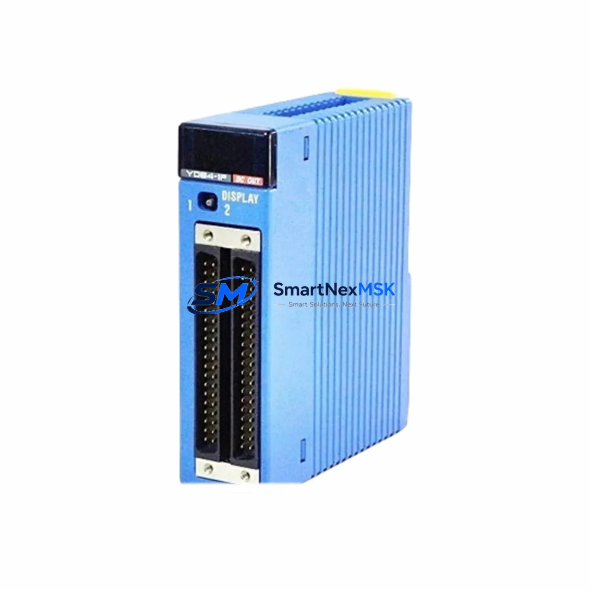
YOKOGAWA F3CR04-ON Retrofit-Ready Ethernet Communication Module for FCN Series Control Systems
The YOKOGAWA F3CR04-ON is a high-performance Ethernet communication module engineered for seamless integration into STARDOM FCN/FCJ series distributed control systems. As legacy automation infrastructure ages and OEM support windows close, the F3CR04-ON has become a critical retrofit component for engineers tasked with modernizing control cabinets, extending system life, and maintaining production continuity without a full platform migration. Whether you are replacing a failed unit, upgrading communication capacity, or migrating from an older protocol stack, the F3CR04-ON delivers verified compatibility, reliable throughput, and a straightforward installation path that minimizes engineering risk and unplanned downtime.
Sourced from authorized distribution channels and subjected to pre-shipment functional testing, every F3CR04-ON unit shipped by SMARTNEXMSK is backed by a 12-month warranty covering manufacturing defects and operational failures under normal industrial conditions. Stock is maintained to support urgent replacement orders, with same-day dispatch available for in-stock units.
Upgrade Compatibility Table
| Parameter | F3CR04-ON Specification | Retrofit Notes |
|---|---|---|
| Compatible Rack / Backplane | STARDOM FCN main unit rack (F3BU04-0N, F3BU16-0N) | Verify slot position; module occupies one standard slot |
| Communication Interface | 100BASE-TX Ethernet (RJ-45) | Confirm switch port speed; auto-negotiation supported |
| Protocol Support | Modbus TCP, OPC-DA, proprietary YOKOGAWA Vnet/IP | Validate SCADA/HMI driver compatibility before cutover |
| Power Consumption | Supplied via backplane (5 VDC, ≤1.5 A) | Check F3PU20-0S or F3PU30-0S power module capacity before adding module |
| Module Address Setting | Rotary switch on module front panel | Match address to original module configuration; document before removal |
| Firmware / OS Compatibility | FCN-RTU firmware R9.04 and above | Upgrade FCN controller firmware if running legacy versions |
| Replacement for Discontinued Models | F3CR04-0N (earlier suffix variant) | Functionally equivalent; confirm suffix with engineering documentation |
| HMI Screen Compatibility | Compatible with FAST/TOOLS R10.x and above | Update tag addresses if slot position changes during retrofit |
| Commissioning Tool | FCN Engineering Tool (EngTool) via USB or Ethernet | Use YOKOGAWA LL100 programming cable for initial configuration if Ethernet unavailable |
| Warranty | 12-Month Warranty — covers manufacturing defects and operational failures under normal industrial use conditions | |
Retrofit Planning for Existing Automation Systems
Successful integration of the F3CR04-ON into an existing control architecture begins well before the physical module swap. Engineers should start by auditing the current FCN rack configuration, documenting every occupied slot, the installed F3BU04-0N or F3BU16-0N backplane revision, and the power budget provided by the active F3PU20-0S or F3PU30-0S power supply module. Insufficient backplane power is one of the most common causes of post-retrofit instability, and it is easily avoided with a pre-installation load calculation.
Terminal wiring on the Ethernet side is straightforward — the F3CR04-ON uses a standard RJ-45 interface — but the network infrastructure must be reviewed. Managed switches should be configured to match the module’s auto-negotiation behavior, and VLAN segmentation should be verified to ensure the FCN controller can reach the SCADA host and any OPC-DA or Modbus TCP clients without routing conflicts. If the existing system uses YOKOGAWA’s Vnet/IP communication backbone, confirm that the F3CR04-ON’s IP address and node number do not conflict with other devices on the segment, including any F3RP61-2L or F3RP71-2L CPU modules already registered in the network configuration.
For sites running YOKOGAWA FAST/TOOLS as the supervisory layer, HMI tag databases should be exported and backed up before the retrofit. If the F3CR04-ON is replacing a module in a different slot position, all associated tag addresses referencing the original slot must be updated in the FAST/TOOLS project and re-downloaded to the HMI server. Similarly, any F3AD04-6R analog input modules or F3YD04-0N digital output modules whose data is routed through the communication module should be verified for correct data mapping post-swap.
I/O expansion planning is also relevant during this phase. If the retrofit is part of a broader system upgrade that includes adding F3AD08-4R high-density analog input modules or F3XD32-3H digital input modules, the additional I/O load must be factored into the backplane power budget and the FCN controller’s scan cycle time. The F3CR04-ON’s Ethernet throughput is sufficient to handle expanded I/O polling without introducing latency, provided the network is properly segmented.
Finally, if the site uses a YOKOGAWA LL100 programming cable for local FCN configuration access, ensure it is available on-site during commissioning. Remote engineering access via Ethernet is preferred for live systems, but a local connection path is essential as a fallback during the cutover window.
Downtime Control During System Migration
Minimizing production interruption during an F3CR04-ON retrofit requires a structured cutover plan executed in coordination with operations and safety teams. The recommended approach is a cold-swap procedure performed during a scheduled maintenance window, with the FCN controller placed in a safe hold state before the module is removed. Before initiating the shutdown, the current FCN application program — including all function block logic, PID tuning parameters, and interlock configurations — should be uploaded from the controller and archived using the FCN Engineering Tool. This backup is the primary recovery asset if the new module requires a full controller re-initialization.
During the physical swap, the rotary address switch on the F3CR04-ON must be set to match the original module’s address before the rack is powered. Failure to do so will cause the FCN controller to report a module address mismatch on startup, requiring an additional configuration cycle. Once the module is seated and the rack is powered, the FCN Engineering Tool should be used to verify that the module is recognized in the correct slot and that its firmware version is compatible with the installed FCN-RTU firmware revision.
Network connectivity should be confirmed before restoring the FCN controller to run mode. A ping test from the engineering workstation to the F3CR04-ON’s configured IP address, followed by a Modbus TCP or OPC-DA poll from the SCADA system, will confirm end-to-end communication integrity. Only after successful communication verification should the FCN controller be returned to run mode and the process brought back online. This staged restart approach protects original program logic, preserves interlock integrity, and maintains field control continuity throughout the migration.
Retrofit Support FAQ
Q: Is the F3CR04-ON a direct drop-in replacement for the earlier F3CR04-0N variant?
A: In most applications, yes. The F3CR04-ON is functionally equivalent to the F3CR04-0N and is designed to occupy the same backplane slot in FCN series racks. However, engineers should verify the firmware revision of the installed FCN controller, as very early firmware versions may require an update to recognize the -ON suffix variant. SMARTNEXMSK technical support can assist with compatibility confirmation prior to order placement.
Q: What commissioning steps are required after installing the F3CR04-ON?
A: After physical installation, set the rotary address switch to match the original module address, power the rack, and connect the FCN Engineering Tool via Ethernet or USB (LL100 cable). Verify module recognition in the slot map, confirm IP address assignment, and perform a communication test from the SCADA or HMI system. If FAST/TOOLS is in use, validate that all tags associated with the module are resolving correctly before returning the controller to run mode.
Q: How is the F3CR04-ON tested before shipment?
A: Every unit undergoes pre-shipment functional testing that includes power-on verification, Ethernet port integrity check, and firmware version confirmation. Units are inspected for physical damage and packaged in anti-static materials. A test report is available upon request. All units are covered by a 12-month warranty from the date of shipment.
Q: Can the F3CR04-ON support both Modbus TCP and OPC-DA simultaneously?
A: Yes. The F3CR04-ON supports concurrent Modbus TCP and OPC-DA connections, subject to the FCN controller’s configured communication load limits. For high-polling-rate applications or systems with multiple SCADA clients, SMARTNEXMSK recommends reviewing the FCN communication load specification in the YOKOGAWA FCN hardware manual to ensure the module is not operating at the upper boundary of its connection capacity.
© 2026 SMARTNEXMSK. All rights reserved.
Original Source: https://smartnexmsk.com
Contact: [email protected] | +86 18259474341



