
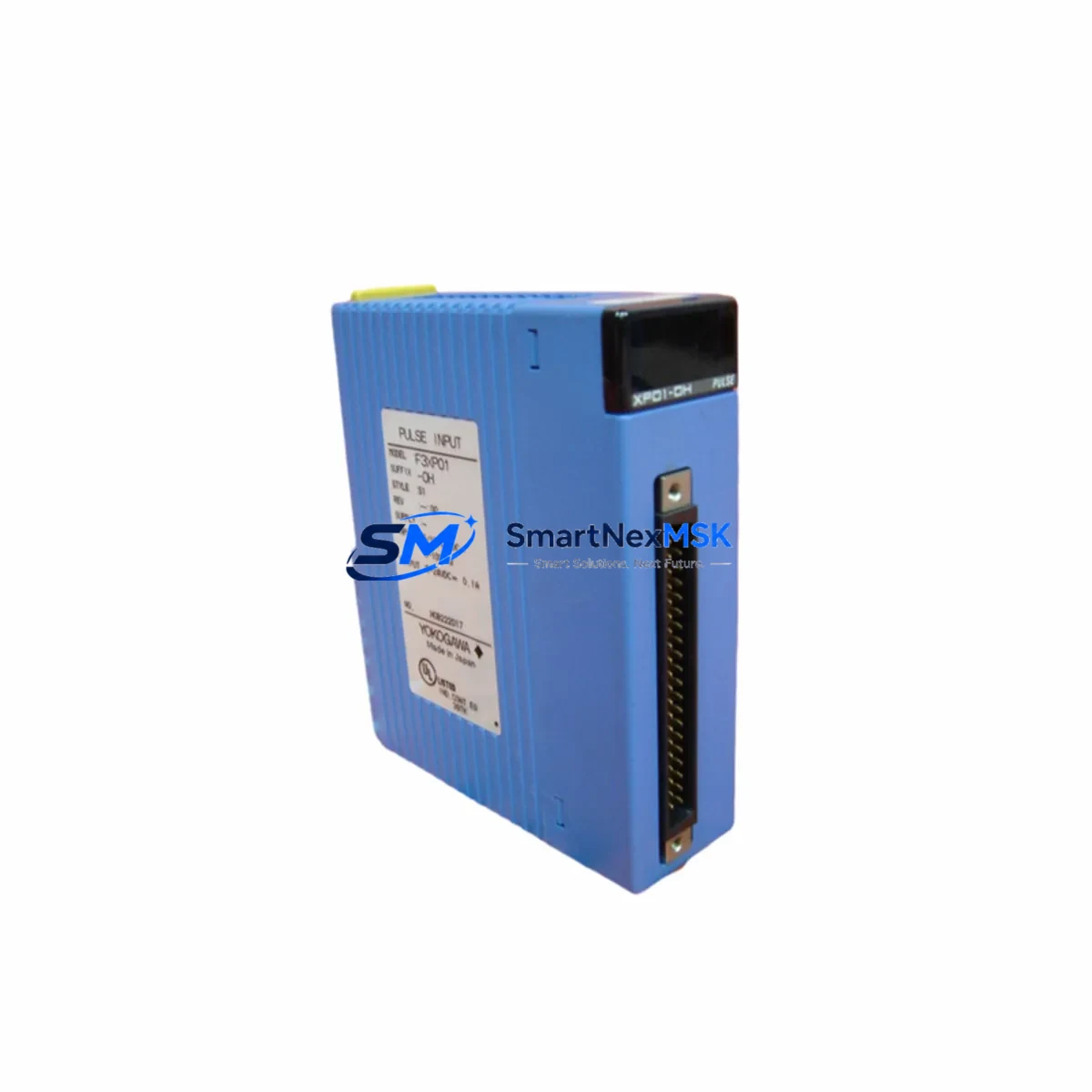
YOKOGAWA F3DA04-1N Spare for FA-M3 Automation: Spare Parts Replacement & Industrial Downtime Risk Control
The YOKOGAWA F3DA04-1N is a 4-channel mixed analog input/output module designed for the FA-M3 modular PLC platform. As a maintenance-ready original spare, it supports rapid field replacement in process control, factory automation, and utility monitoring applications where analog signal integrity is critical to continuous operation. Whether you are managing a scheduled shutdown, responding to an unplanned fault, or building a strategic spare parts inventory, the F3DA04-1N delivers the compatibility, reliability, and traceability that maintenance and procurement engineers require.
Sourced directly from authorized supply chains, each unit undergoes functional verification prior to dispatch. All F3DA04-1N modules are shipped with a 12-month warranty covering manufacturing defects and operational failures under normal industrial use conditions. Fast lead times and in-stock availability ensure that your FA-M3 system can be restored to full operation with minimal downtime exposure.
Spare Maintenance Table
| Parameter | Specification / Detail |
|---|---|
| SKU / Part Number | F3DA04-1N |
| Brand | YOKOGAWA |
| Series | FA-M3 (F3 Series Modular PLC) |
| Module Type | 4-Channel Mixed Analog I/O (Input + Output) |
| Analog Inputs | 2 channels (voltage / current selectable) |
| Analog Outputs | 2 channels (voltage / current selectable) |
| Input Signal Range | 0–5 V, 1–5 V, 0–10 V, 4–20 mA (configurable) |
| Output Signal Range | 0–5 V, 1–5 V, 0–10 V, 4–20 mA (configurable) |
| Resolution | 12-bit (typical FA-M3 analog module standard) |
| Isolation | Channel-to-channel and channel-to-bus isolation |
| Power Consumption | Supplied via FA-M3 backplane bus |
| Mounting | FA-M3 base unit slot (F3BU-series compatible) |
| Operating Temperature | 0°C to 55°C |
| Storage Temperature | -20°C to 70°C |
| Humidity | 10% to 90% RH (non-condensing) |
| Country of Origin | Japan |
| Compatibility | FA-M3 F3BU04-0N, F3BU08-0N, F3BU16-0N base units; all F3 series CPU modules |
| Application Environment | Process control, factory automation, utility monitoring, HVAC, water treatment |
| Maintenance Recommendation | Inspect terminal wiring, shield grounding, and signal calibration at each planned maintenance interval |
| Warranty | 12 months from date of shipment |
| Condition | Original, new or tested-serviceable; functionally verified before dispatch |
Maintenance Planning for Continuous Operation
When replacing the F3DA04-1N in an FA-M3 control cabinet, a thorough maintenance review of the surrounding system is essential to prevent repeat failures and ensure signal chain integrity. Maintenance engineers should treat the analog I/O module replacement as an opportunity to inspect the entire electrical loop.
Begin with the FA-M3 power supply module (such as the F3PU20-0S or F3PU10-0S) — verify output voltage stability and check for ripple or thermal stress indicators. A degraded power supply is a common root cause of analog signal drift and module faults. Next, inspect the FA-M3 CPU module (e.g., F3SP71-4N or F3SP66-4S) for firmware version compatibility with the replacement F3DA04-1N, particularly if the system has been running legacy software.
Review the terminal block wiring connected to the analog channels — loose or corroded terminals on F3-series screw-type or spring-clamp terminal blocks are a frequent source of signal noise and measurement error. If the system uses signal isolators (such as YOKOGAWA MTL or equivalent DIN-rail isolators) between field transmitters and the F3DA04-1N inputs, verify isolator output calibration and check for loop power supply adequacy.
For output channels driving control valves or variable frequency drives, inspect the analog output wiring for correct shielding and grounding. Unshielded runs in high-EMI environments can introduce offset errors that are misdiagnosed as module failures. Check the F3 series communication module (e.g., F3LC11-1F Ethernet module or F3LP02-0N PROFIBUS module) to confirm that the control network remains stable after the module swap — a slot reassignment can affect I/O mapping in the CPU program.
If the cabinet includes relay output modules (such as F3YR04-0N) or digital I/O modules (F3XD32-3H or F3YD32-3H) in adjacent slots, verify that the backplane bus connector seating is secure after the F3DA04-1N is installed. Loose backplane connections can cause intermittent faults across multiple modules. Finally, if the system uses an FA-M3 HMI or SCADA interface, confirm that analog tag scaling and engineering unit conversion parameters are correctly configured for the replacement module’s channel assignments.
Building a minimum viable spare parts kit around the F3DA04-1N should also include at least one spare FA-M3 power supply module, a spare CPU module of the same firmware generation, and a set of terminal block connectors matching the field wiring gauge. This approach reduces mean time to repair (MTTR) and supports a proactive maintenance culture aligned with IEC 62443 and ISO 55001 asset management principles.
Site Replacement Workflow
Step 1 — Pre-replacement verification: Confirm the replacement F3DA04-1N SKU matches the installed module label exactly. Cross-reference the FA-M3 system configuration file (WideField3 or WideField2 project) to identify the slot address and I/O channel assignments for the module being replaced.
Step 2 — Safe isolation: Place the FA-M3 CPU in STOP mode via the WideField programming tool or the front-panel RUN/STOP switch. De-energize field instruments connected to the analog channels using the appropriate loop isolation procedure. Do not remove the module under power if the base unit does not support hot-swap for this module type.
Step 3 — Physical replacement: Remove the faulty F3DA04-1N by releasing the module locking lever and sliding it out of the base unit slot. Insert the replacement module firmly until the locking lever engages. Reconnect the field wiring terminal block, verifying wire positions against the as-built wiring diagram.
Step 4 — System restart and verification: Return the CPU to RUN mode. Monitor the analog input and output values in the WideField online monitor or SCADA system to confirm signal accuracy. Perform a loop calibration check if the process requires traceable measurement accuracy. Document the replacement in the maintenance management system (CMMS) with the new module serial number and installation date.
Step 5 — Post-replacement monitoring: Monitor the replaced module for the first 24–72 hours of operation to detect any latent wiring or configuration issues. Update the spare parts inventory record to trigger reorder of a replacement F3DA04-1N to maintain minimum stock levels.
Spare Parts Support FAQ
Q1: Is the F3DA04-1N compatible with all FA-M3 base units?
The F3DA04-1N is compatible with all standard FA-M3 base units in the F3BU series, including the F3BU04-0N (4-slot), F3BU08-0N (8-slot), and F3BU16-0N (16-slot) configurations. It is not compatible with the older F2 series or the STARDOM FCN/FCJ platforms. Always verify the base unit model and CPU firmware version before installation to ensure full functional compatibility.
Q2: What pre-shipment testing is performed on the F3DA04-1N?
Each F3DA04-1N unit is functionally tested prior to dispatch. Testing includes power-on verification, analog input signal accuracy check across the configured range, analog output signal verification, and bus communication confirmation. Units that do not pass functional verification are not shipped. A test report can be provided upon request for quality-critical applications.
Q3: How should the F3DA04-1N be stored as a long-term spare?
Store the module in its original anti-static packaging in a dry, temperature-controlled environment (10°C to 30°C, 20%–70% RH non-condensing). Avoid storage near strong magnetic fields or corrosive atmospheres. Inspect stored modules annually for physical damage and verify functional status before committing to installation in a live system. Long-term storage beyond 3 years should include a pre-installation functional test.
Q4: What does the 12-month warranty cover?
The 12-month warranty covers manufacturing defects and operational failures under normal industrial operating conditions as specified in the YOKOGAWA FA-M3 hardware manual. It does not cover damage resulting from incorrect installation, overvoltage, reverse polarity, physical impact, or use outside the rated environmental specifications. Warranty claims are processed through our technical support team with return merchandise authorization (RMA). Replacement or repair is provided at no charge for valid warranty claims within the coverage period.
© 2026 SMARTNEXMSK. All rights reserved.
Original Source: https://smartnexmsk.com
Contact: [email protected] | +86 18259474341



