
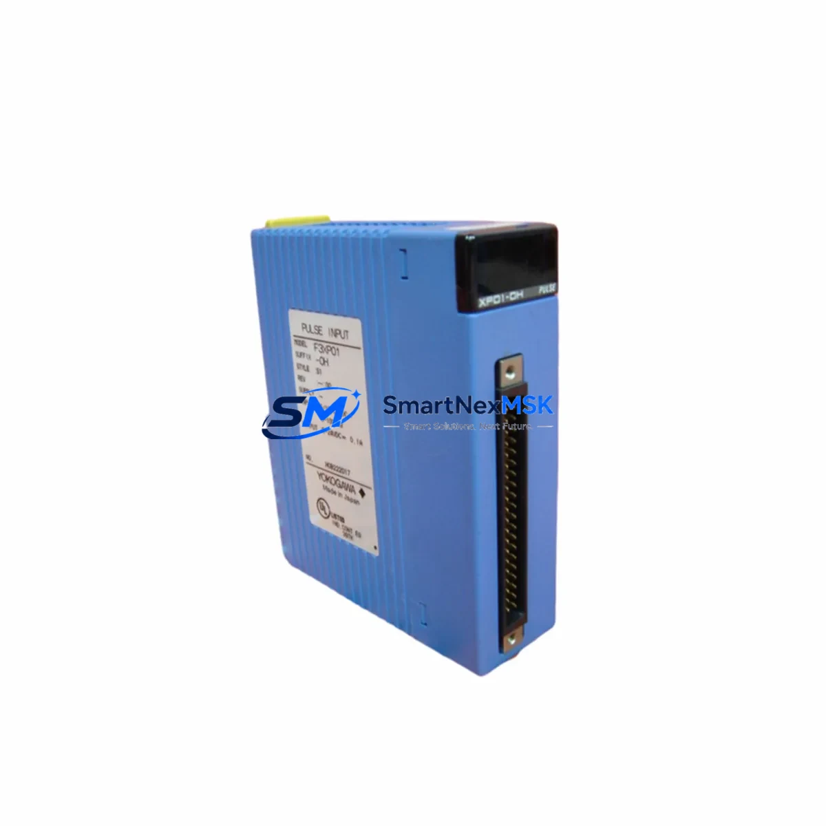
YOKOGAWA F3LC11-1N Retrofit-Ready Computer Link Module for FA-M3 Control Systems
The YOKOGAWA F3LC11-1N is a Computer Link Module designed for the FA-M3 Series programmable logic controller platform — one of YOKOGAWA’s most widely deployed process and factory automation architectures. As legacy FA-M3 installations age and original spare parts become increasingly difficult to source, the F3LC11-1N has become a critical retrofit component for engineers managing aging control infrastructure across chemical plants, power utilities, food processing lines, and discrete manufacturing facilities.
This module provides a high-speed serial communication link between the FA-M3 CPU — such as the F3SP28-3N, F3SP38-6N, or F3SP58-6S — and host computers, SCADA systems, or supervisory HMI platforms. It supports the YOKOGAWA Computer Link protocol over RS-232C and RS-422/485 interfaces, enabling reliable data exchange with legacy DCS nodes, historian servers, and operator stations without requiring protocol conversion middleware.
For sites currently running discontinued modules or modules approaching end-of-support, the F3LC11-1N offers a validated drop-in replacement path within the same FA-M3 rack architecture. Engineers can retain existing F3BU04-0N or F3BU16-0N base units, preserving rack wiring, terminal block assignments, and slot addressing — dramatically reducing retrofit labor and commissioning risk.
Upgrade Compatibility Table
| Parameter | Details |
|---|---|
| Compatible Series | YOKOGAWA FA-M3 (F3 Series) |
| Replaces / Upgrades | F3LC11-0N, F3LC12-1N (older Computer Link variants) |
| Communication Interface | RS-232C (1 port) / RS-422/485 selectable |
| Protocol | YOKOGAWA Computer Link (1:1 and 1:N) |
| Rack / Backplane | FA-M3 standard backplane; compatible with F3BU04-0N, F3BU08-0N, F3BU16-0N |
| Slot Installation | Any I/O slot; module address set via rotary switch |
| Power Consumption | 5 VDC from backplane (verify PSU capacity: F3PU01-0S or F3PU02-0S) |
| CPU Compatibility | F3SP28-3N, F3SP38-6N, F3SP58-6S, F3SP67-6S and compatible FA-M3 CPUs |
| Program Compatibility | Existing ladder logic communication instructions retained; verify SEND/RECV block parameters |
| HMI / SCADA Impact | Station number and baud rate must match existing HMI configuration (e.g., YOKOGAWA WT Series, ProSafe-RS nodes) |
| Warranty | 12 Months — covers manufacturing defects, functional failure under normal operating conditions |
| Condition | New / Tested Surplus / Refurbished (specify at order) |
| Origin | Japan |
Retrofit Planning for Existing Automation Systems
Successful integration of the F3LC11-1N into an existing FA-M3 control cabinet begins with a thorough pre-retrofit audit. Engineers should document the current slot map of the base unit, noting the positions of all installed modules — including F3XD32-3H digital input modules, F3YD32-3H digital output modules, F3AD04-1M analog input modules, and any existing F3LC-series communication modules — before removing any hardware.
Power budget verification is essential. The FA-M3 power supply module — typically an F3PU01-0S (5 VDC, 5 A) or F3PU02-0S (5 VDC, 8 A) — must have sufficient headroom to support the F3LC11-1N alongside all co-installed I/O modules. Calculate total current draw from the module specification sheets and confirm the PSU is not already operating near its rated capacity.
Terminal wiring for the RS-232C or RS-422/485 port should be mapped against the existing cable schedule. If the site previously used an F3LC11-0N, the DB9 or terminal block pinout may differ slightly — verify TXD, RXD, RTS, CTS, SG assignments against the F3LC11-1N hardware manual before reconnecting field cables. For RS-422/485 multi-drop configurations, confirm termination resistor settings and verify that all node addresses are unique across the communication segment.
Module address assignment on the F3LC11-1N is performed via the onboard rotary switch prior to installation. This address must correspond to the station number referenced in the FA-M3 CPU ladder program’s SEND and RECV communication function blocks. Mismatched addresses are the most common cause of communication failure during initial commissioning and should be verified before powering the rack.
If the control system includes an F3RP61-2L or F3RP71-2N Linux-based controller module sharing the same base unit, confirm that the communication channel allocation in the system configuration tool does not conflict with the F3LC11-1N’s assigned slot. Similarly, if a YOKOGAWA Exaopc OPC server or a third-party SCADA gateway is connected via the Computer Link port, update the server’s device configuration to reflect any changes in baud rate, parity, or station addressing introduced during the swap.
For sites migrating from older F3LC12-1N modules, note that the F3LC11-1N supports the same Computer Link protocol command set, making it fully backward-compatible with existing host-side communication software. No changes to the SCADA polling logic or historian tag configuration are typically required, provided the physical layer settings (baud rate, data bits, stop bits, parity) are preserved.
Downtime Control During System Migration
Minimizing unplanned downtime during an FA-M3 module swap requires a structured hot-swap preparation protocol, even though the FA-M3 platform does not support live module replacement under power. The recommended approach is to schedule the swap during a planned maintenance window and prepare a complete pre-tested replacement module before the line is taken offline.
Prior to shutdown, use the FA-M3 programming tool (WideField3 or WideField2) to upload and archive the current CPU program, including all data registers, communication parameters, and I/O force tables. Store a verified backup on an offline engineering workstation. This ensures that if the CPU — such as an F3SP58-6S — requires a cold restart after the module swap, the program can be reloaded within minutes rather than hours.
During the swap, label all terminal block wiring before disconnection. Photograph the existing cable routing inside the control cabinet. Install the F3LC11-1N in the same slot as the removed module, confirm the rotary address switch setting, and reconnect all field cables per the verified wiring schedule. Power the rack and observe the module’s LED status indicators — the RUN LED should illuminate green within the normal startup sequence.
After power-up, initiate a communication test from the host SCADA or HMI system. Verify that all monitored tags are updating at the expected scan rate and that no communication error flags are active in the CPU’s diagnostic registers. If the site uses a YOKOGAWA CENTUM VP or ProSafe-RS system as the supervisory layer, confirm that the FA-M3 node appears online in the system’s network status display before releasing the line back to production.
For critical processes where even a brief communication interruption is unacceptable, consider pre-staging a parallel communication path using a temporary F3LC11-1N on a secondary base unit, validating the configuration offline before the final cutover. This approach is particularly effective in pharmaceutical batch control and continuous chemical process environments where control continuity is a regulatory requirement.
Retrofit Support FAQ
Q1: Is the F3LC11-1N a direct drop-in replacement for the F3LC11-0N?
In most FA-M3 installations, yes. Both modules occupy a standard FA-M3 I/O slot and use the same Computer Link protocol. However, verify the hardware revision of your base unit and confirm that the communication port pinout and rotary address switch positions are consistent between the two variants before finalizing the swap. Minor differences in LED labeling and terminal block layout may exist between hardware generations.
Q2: What commissioning steps are required after installing the F3LC11-1N?
After physical installation, confirm the module address switch matches the station number in the CPU ladder program. Power the rack and verify the RUN LED status. From the host computer or SCADA system, initiate a communication test using the Computer Link read command (e.g., random read of a known data register). Check the CPU’s communication error register (typically accessible via WideField3 online monitoring) for any fault codes. Adjust baud rate, parity, or stop bit settings in both the module and the host if communication is not established on the first attempt.
Q3: Can the F3LC11-1N be used in an FA-M3 system that also includes Ethernet modules?
Yes. The FA-M3 backplane supports simultaneous installation of multiple communication modules, including F3LE01-5T Ethernet interface modules and F3LC11-1N Computer Link modules, provided the total power budget of the PSU is not exceeded. Each module operates independently on the backplane, and the CPU addresses them by slot position and module type. No protocol conflicts occur between Computer Link and Ethernet communication channels.
Q4: What does the 12-month warranty cover, and what is the return process?
The 12-month warranty covers manufacturing defects and functional failures under normal operating conditions, including communication port failure, backplane interface faults, and LED indicator malfunctions. It does not cover damage resulting from incorrect installation, overvoltage, or physical impact. To initiate a warranty claim, contact our sales team with the order reference number and a description of the fault. We will arrange return shipping and provide a tested replacement or full refund within the agreed service timeline.
© 2026 SMARTNEXMSK. All rights reserved.
Original Source: https://smartnexmsk.com
Contact: [email protected] | +86 18259474341



