
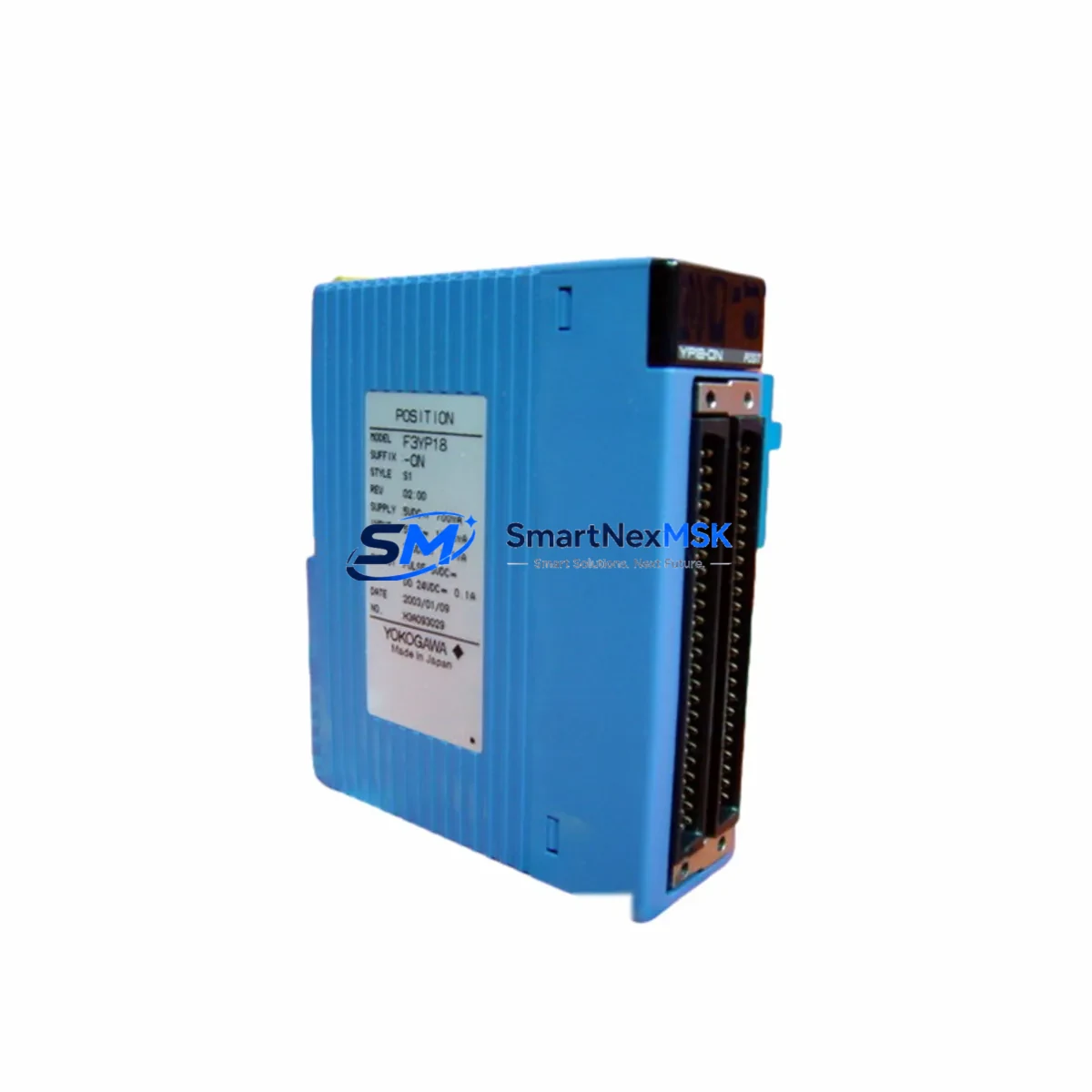
YOKOGAWA F3LC21-1N Retrofit-Ready Multi-Link Communication Module for FA-M3 Control Systems
The YOKOGAWA F3LC21-1N is a Multi-Link Communication Module engineered for the FA-M3 series programmable logic controller platform — one of Yokogawa’s most widely deployed process automation architectures in petrochemical, power generation, pharmaceutical, and discrete manufacturing environments. As legacy FA-M3 installations age and original communication modules approach end-of-life, the F3LC21-1N has become a critical retrofit component for engineers tasked with extending system lifespan, restoring communication integrity, and bridging older control architectures to modern supervisory and SCADA layers without full system replacement.
SMARTNEXMSK maintains verified stock of the F3LC21-1N and ships from Xiamen with full functional testing, documentation, and a 12-month warranty covering manufacturing defects and operational failures under normal industrial conditions.
Upgrade Compatibility Table
| Parameter | F3LC21-1N Specification | Retrofit Notes |
|---|---|---|
| Module Type | Multi-Link Communication Module | Direct slot replacement in FA-M3 base units |
| Compatible Rack / Backplane | FA-M3 F3SP, F3BU series base units | Verify slot assignment and base unit revision before installation |
| Communication Protocol | Yokogawa Multi-Link (proprietary) | Compatible with existing FA-M3 Multi-Link network topology; no protocol migration required |
| Power Consumption | Supplied via backplane 5 VDC bus | Confirm power supply module (e.g. F3PU20-0S or F3PU30-0S) has sufficient remaining capacity before adding module |
| Module Address / Station No. | Configurable via rotary switch on module face | Match original station number from decommissioned module; update CPU scan list if required |
| Connector / Terminal Interface | D-Sub 9-pin (RS-422 compatible) | Retain original cable harness; verify pin-out against wiring diagram before reconnection |
| CPU Program Compatibility | FA-M3 ToolBox / WideField3 ladder logic | No program modification required for direct replacement; re-download may be needed after module swap |
| HMI / SCADA Integration | Compatible with Yokogawa ProSafe-RS, FAST/TOOLS, and third-party OPC DA/UA gateways | Verify HMI tag addresses and communication driver settings post-installation |
| Replacement Candidates | F3LC11-1N, F3LC21-0N (earlier revisions) | Confirm firmware revision compatibility with CPU module before substitution |
| Warranty | 12-Month Warranty — covers manufacturing defects and operational failures under normal industrial use conditions | |
Retrofit Planning for Existing Automation Systems
Replacing a communication module in a live FA-M3 system requires methodical pre-work to avoid unplanned downtime and data loss. Before removing the existing F3LC21-1N or its predecessor, engineers should document the current module slot position within the F3BU04-0N or F3BU16-0N base unit, record the rotary switch station address, and photograph all terminal wiring and cable routing. The FA-M3 CPU module — typically an F3SP71-4S, F3SP76-7S, or F3SP66-4S — should have its current ladder program backed up via WideField3 programming software before any hardware intervention begins.
Power budget verification is a mandatory step. The F3PU20-0S or F3PU30-0S power supply module feeding the base unit must have sufficient 5 VDC headroom to support the replacement F3LC21-1N. If the existing installation is already near capacity — common in fully populated 16-slot base units — a power supply upgrade or load redistribution across a secondary base unit may be required before the communication module swap proceeds.
For systems where the F3LC21-1N participates in a Multi-Link network connecting multiple FA-M3 racks, the network topology map should be reviewed. Each node’s station number must remain consistent with the CPU’s I/O assignment table. If the original module’s station number is unknown due to missing documentation, it can often be recovered from the WideField3 project file’s network configuration screen or from the SCADA historian’s communication log.
In installations where the FA-M3 communicates upstream to a Yokogawa CENTUM VP DCS or interfaces with a ProSafe-RS safety controller via the Vnet/IP or FL-net backbone, the F3LC21-1N’s role as a gateway or pass-through node must be clearly understood before replacement. Disrupting the communication link — even briefly — can trigger alarms in the supervisory layer. Coordinate with the DCS operator and confirm that the FAST/TOOLS or Exaquantum historian is set to buffer data during the maintenance window.
For sites migrating from older F3LC11-1N modules to the F3LC21-1N, the physical form factor is identical and the backplane interface is backward compatible. However, engineers should verify that the FA-M3 CPU firmware version supports the F3LC21-1N’s extended diagnostic register set. If the CPU is running an early firmware revision, a firmware update via the F3CF04-1N CF card or direct WideField3 download may be required. Additionally, any F3AD04-6R analog input modules or F3DA04-6R analog output modules sharing the same base unit should be confirmed as unaffected by the communication module swap before the maintenance window closes.
Where the control system includes remote I/O expansion via F3LE01-5T Ethernet modules or F3LP02-0N PROFIBUS-DP modules, verify that the F3LC21-1N’s Multi-Link traffic does not conflict with the remote I/O polling cycle. In high-density installations, scan time adjustments in the CPU configuration may be necessary to maintain deterministic response times across all communication channels.
Downtime Control During System Migration
Minimizing production downtime during an FA-M3 communication module replacement requires a structured maintenance window plan. The recommended approach is a cold-swap procedure executed during a scheduled shutdown: power down the base unit, remove the failed or end-of-life F3LC21-1N, install the replacement module, verify the station address switch setting, reconnect all cables, and restore power. Total physical swap time for an experienced technician is typically under 15 minutes.
Before powering down, the FA-M3 CPU should be placed in STOP mode via the WideField3 online monitor or the physical RUN/STOP switch on the CPU module faceplate. This prevents the CPU from executing scan cycles against a missing communication module and avoids spurious fault codes being written to the error log. After the replacement module is seated and powered, the CPU should be returned to RUN mode and the Multi-Link network status confirmed via the F3LC21-1N’s LED indicators — specifically the RUN, ERR, and LINK status LEDs on the module face.
If the system cannot be taken offline, a hot-swap procedure may be possible depending on the FA-M3 base unit revision and CPU firmware version. Consult the FA-M3 hardware manual (IM 34M06H11-01E) for slot-specific hot-swap support before attempting live module replacement. In either case, the original ladder program logic stored in the CPU’s battery-backed RAM is preserved across the module swap and does not require re-download unless the CPU was also replaced or its memory cleared.
Post-swap commissioning should include a full communication link test, verification of all Multi-Link station responses, confirmation of HMI tag data refresh, and a review of the CPU error log for any residual fault codes. If the system interfaces with a Yokogawa CENTUM VP or third-party SCADA via OPC, confirm that the OPC server re-establishes its connection and that all process variable tags are updating correctly before releasing the system back to production.
Retrofit Support FAQ
Q1: Is the F3LC21-1N a direct drop-in replacement for the F3LC11-1N?
In most FA-M3 installations, yes. The F3LC21-1N shares the same physical form factor and backplane connector as the F3LC11-1N and is backward compatible with the FA-M3 Multi-Link network protocol. However, engineers should verify that the host CPU module’s firmware version supports the F3LC21-1N’s diagnostic register set. If the CPU firmware is below the minimum supported revision, a firmware update is required before the replacement module will initialize correctly.
Q2: What wiring changes are required when installing the F3LC21-1N?
For direct replacement of an existing F3LC21-1N or F3LC11-1N, no wiring changes are required. The D-Sub 9-pin RS-422 connector and cable harness from the original installation can be reused. Verify pin-out continuity with a multimeter before reconnection if the cable has been disturbed or if the installation is more than five years old. For new installations, refer to the FA-M3 Multi-Link wiring diagram in the hardware manual (IM 34M06H11-01E) for correct shielding and termination resistor placement.
Q3: How is the module station address configured, and does it need to match the original?
The station address is set via a rotary switch on the F3LC21-1N module faceplate, accessible without removing the module from the base unit. The replacement module’s station address must match the original module’s address exactly. If the original address is unknown, it can be recovered from the WideField3 project file’s network configuration screen or from the CPU’s I/O assignment table. An incorrect station address will cause the CPU to report a communication error and the affected Multi-Link network segment will not initialize.
Q4: What does the 12-month warranty cover, and what is the process for a warranty claim?
The 12-month warranty covers manufacturing defects and operational failures under normal industrial use conditions from the date of shipment. It does not cover damage resulting from incorrect installation, overvoltage, physical impact, or use outside the module’s rated environmental specifications. To initiate a warranty claim, contact SMARTNEXMSK at [email protected] with the order number, module serial number, and a description of the failure. Replacement units are dispatched after fault verification, and return shipping of the defective module is required for warranty processing.
© 2026 SMARTNEXMSK. All rights reserved.
Original Source: https://smartnexmsk.com
Contact: [email protected] | +86 18259474341



