
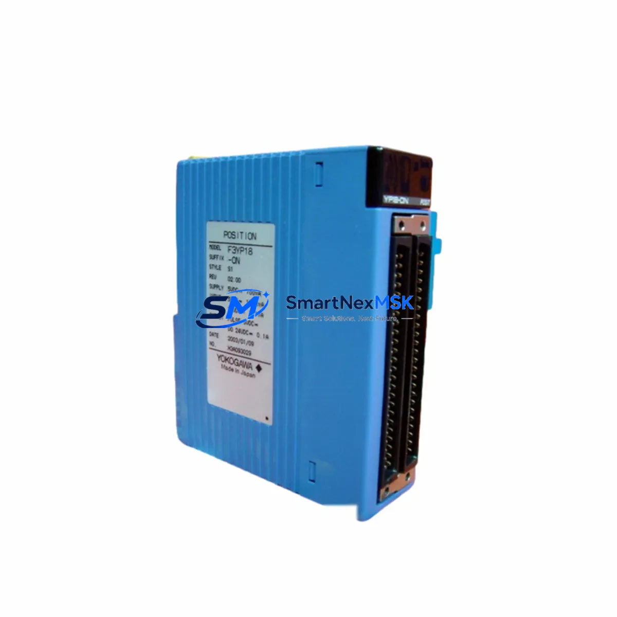
YOKOGAWA F3LE01-5T Spare for FA-M3 Automation: Spare Replacement & Industrial Downtime Risk Control
The YOKOGAWA F3LE01-5T is a 10BASE-T/100BASE-TX Ethernet communication module designed for the FA-M3 Range-free Multi-controller platform. In industrial environments where network-based SCADA integration, remote I/O polling, and real-time data exchange are mission-critical, the F3LE01-5T serves as the primary communication bridge between the FA-M3 CPU rack and plant-level Ethernet networks. Unplanned failure of this module can immediately disrupt production monitoring, alarm management, and supervisory control — making a verified, ready-to-ship spare an essential element of any maintenance strategy.
This listing provides an original YOKOGAWA F3LE01-5T spare part, sourced from authorized supply channels, fully tested prior to shipment, and backed by a 12-month warranty. It is suitable for direct slot-in replacement within FA-M3 control racks without hardware modification, provided firmware and CPU module compatibility are confirmed during pre-installation checks.
Spare Maintenance Table
| Parameter | Specification |
|---|---|
| Part Number | F3LE01-5T |
| Brand | YOKOGAWA |
| Series | FA-M3 Range-free Multi-controller |
| Module Type | Ethernet Communication Module |
| Network Standard | 10BASE-T / 100BASE-TX (IEEE 802.3) |
| Connector | RJ-45 (×1) |
| Supported Protocols | TCP/IP, UDP/IP, Modbus/TCP, FL-net |
| Max Connections | 16 simultaneous TCP connections |
| Power Consumption | 5 VDC, ≤1.0 A (from backplane) |
| Operating Temperature | 0 °C to 55 °C |
| Humidity | 10% to 90% RH (non-condensing) |
| Mounting | FA-M3 base unit slot (any I/O slot) |
| Compatibility | FA-M3 F3SP22, F3SP28, F3SP38, F3SP53, F3SP58, F3SP67, F3SP71, F3SP76 CPU modules |
| Origin | Japan |
| Condition | Original, New / Tested Surplus |
| Pre-shipment Test | Power-on, LED status, communication loop-back verified |
| Warranty | 12 Months |
| Delivery | Express international shipping available |
Maintenance Planning for Continuous Operation
When a maintenance or procurement engineer schedules replacement of the F3LE01-5T, the inspection scope should extend beyond the module itself. A thorough control cabinet audit during the same maintenance window significantly reduces the risk of secondary failures and repeat downtime events.
Begin with the FA-M3 CPU module (such as the F3SP71-4S or F3SP76-7S) — confirm firmware version compatibility with the F3LE01-5T and verify that the CPU’s communication parameter tables are intact and correctly mapped to the replacement module’s IP address. Alongside the CPU, inspect the FA-M3 power supply module (F3PU20-0S or F3PU30-0S) for output voltage stability; a degraded power supply is a common root cause of intermittent Ethernet module faults that are misdiagnosed as module failure.
Check the FA-M3 base unit (backplane) — particularly the slot connector pins and backplane bus integrity — since physical damage to the backplane can cause communication errors even after a module swap. If the control cabinet includes F3NC96-0N or F3NC32-0N network communication modules for FL-net or PROFIBUS integration, verify their status simultaneously, as these modules share the same communication infrastructure and are often affected by the same network disturbances that degrade the F3LE01-5T.
For the Ethernet circuit itself, inspect the industrial Ethernet switch or managed switch connected to the F3LE01-5T’s RJ-45 port. Port negotiation mismatches (auto-negotiation vs. fixed 100 Mbps full-duplex) are a frequent cause of packet loss that can trigger false module alarms. Replace or re-terminate Cat5e/Cat6 shielded Ethernet patch cables within the cabinet — cable degradation is often overlooked during module-focused maintenance.
If the FA-M3 system interfaces with field instruments via F3AD08-6M analog input modules or F3DA04-1M analog output modules, verify that signal integrity has not been compromised by the same electrical disturbance that caused the Ethernet module fault. Similarly, inspect F3YD32-0T digital output modules and associated relay output terminals for contact wear, particularly in high-cycle applications. For systems using F3RP61-2L or F3RP71-2L Linux-based CPU modules in hybrid configurations, confirm that the Ethernet routing tables and socket communication settings remain consistent after the module replacement.
Finally, review the terminal blocks and wiring harnesses within the control cabinet. Loose or corroded terminal connections on power distribution rails can introduce ground loops that degrade Ethernet communication performance. A complete spare parts kit for an FA-M3 Ethernet-enabled control system should include at minimum: one F3LE01-5T module, one power supply module, one set of Ethernet patch cables, and a spare CPU module — ensuring that any single-point failure can be resolved within one maintenance shift.
Site Replacement Workflow
Step 1 — Pre-replacement verification: Before removing the existing F3LE01-5T, document the current IP address, subnet mask, gateway, and all communication parameter settings using YOKOGAWA’s WideField3 or ToolBox software. Export the CPU program and communication configuration as a backup.
Step 2 — Safe module removal: Power down the FA-M3 base unit or, if hot-swap is supported by the specific base unit model, follow YOKOGAWA’s hot-swap procedure. Remove the F3LE01-5T by releasing the module locking lever and sliding it out of the slot. Inspect the slot connector for bent pins or contamination before inserting the replacement.
Step 3 — Replacement module installation: Insert the new F3LE01-5T into the same slot. Restore power and observe the module’s LED indicators — the RUN LED should illuminate green within 30 seconds of power-on. If the ERR LED remains lit, re-check the communication parameter settings via WideField3.
Step 4 — Communication parameter restore: Using WideField3, re-enter or download the previously backed-up IP address, protocol settings, and connection parameters to the replacement module. Perform a ping test from the SCADA/HMI workstation to confirm network connectivity before resuming production.
Step 5 — System validation: Run a full I/O check cycle, verify that all SCADA tags are updating correctly, and confirm that FL-net or Modbus/TCP polling is operating at the expected cycle time. Log the replacement in the maintenance record system with the new module’s serial number and installation date.
This workflow minimizes mean time to repair (MTTR) and ensures system compatibility is maintained without requiring a full PLC program reload, preserving production continuity and reducing the risk of configuration errors during emergency replacements.
Spare Parts Support FAQ
Q1: Is this F3LE01-5T compatible with all FA-M3 CPU modules?
The F3LE01-5T is compatible with the majority of FA-M3 CPU modules, including the F3SP22, F3SP28, F3SP38, F3SP53, F3SP58, F3SP67, F3SP71, and F3SP76 series. Compatibility with specific firmware versions should be confirmed against YOKOGAWA’s compatibility matrix (available in the F3LE01-5T user manual, IM 34M06H46-01E). We recommend providing your CPU module part number when placing an order so our technical team can confirm compatibility before shipment.
Q2: What pre-shipment testing is performed on this module?
Every F3LE01-5T unit undergoes power-on testing, LED status verification, and Ethernet loop-back communication testing before dispatch. Units that do not pass all test criteria are not shipped. A test report is available upon request. The module is shipped in anti-static packaging with protective end caps to prevent connector damage during transit.
Q3: How should I manage F3LE01-5T inventory for long-term system support?
For FA-M3 systems with Ethernet-dependent SCADA or remote I/O architectures, we recommend maintaining a minimum of one F3LE01-5T spare per control system. For multi-rack or multi-cabinet installations, a ratio of one spare per three installed modules is a practical benchmark. Given that YOKOGAWA has transitioned some FA-M3 components to limited-availability status, securing long-term spare inventory now reduces procurement risk for systems with 5–15 year operational horizons.
Q4: What does the 12-month warranty cover, and what is the replacement process?
The 12-month warranty covers manufacturing defects and functional failures under normal operating conditions (within specified temperature, humidity, and voltage ranges). It does not cover damage caused by incorrect installation, overvoltage, physical impact, or unauthorized modification. In the event of a warranty claim, contact our support team with the order number and a description of the fault. We will arrange for a replacement unit to be dispatched after fault verification, minimizing your system downtime.
© 2026 SMARTNEXMSK. All rights reserved.
Original Source: https://smartnexmsk.com
Contact: [email protected] | +86 18259474341



