
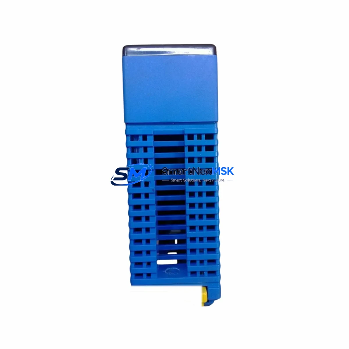
YOKOGAWA F3LX02-1N Spare for FA-M3 Automation: Spare Parts Replacement & Industrial Downtime Risk Control
The YOKOGAWA F3LX02-1N is an original interface module designed for the FA-M3 modular PLC platform — one of the most widely deployed process automation controllers in petrochemical, power generation, pharmaceutical, and discrete manufacturing facilities. When this module fails or degrades, the impact on production continuity is immediate. Sourcing a verified, tested replacement unit is the fastest path to restoring normal operation without compromising system integrity.
This listing provides a maintenance-ready, original YOKOGAWA F3LX02-1N spare part, fully tested prior to shipment, backed by a 12-month warranty, and available for rapid dispatch to minimize unplanned downtime. Whether you are executing a planned shutdown replacement, responding to an emergency fault, or building a strategic spare parts inventory for your FA-M3 control system, this unit is ready to deploy.
Spare Maintenance Table
| Parameter | Specification / Detail |
|---|---|
| Part Number / SKU | F3LX02-1N |
| Brand | YOKOGAWA Electric Corporation |
| Series | FA-M3 (STARDOM / FA-M3R compatible) |
| Module Type | PLC Interface Module |
| Country of Origin | Japan |
| Compatibility | FA-M3 base units and expansion racks; compatible with F3SP series CPU modules |
| Installation | DIN rail / rack-mount into FA-M3 backplane slot; hot-swap subject to system configuration |
| Operating Environment | 0–55 °C ambient; 10–90% RH non-condensing; IEC 61131-2 compliant |
| Power Consumption | Per FA-M3 rack power budget; verify with F3PU series power supply module rating |
| Maintenance Recommendation | Inspect connector pins, backplane contacts, and LED status indicators during scheduled PM; replace if intermittent communication faults are logged |
| Warranty | 12 Months from date of shipment |
| Pre-shipment Testing | Functional test performed; unit verified operational before dispatch |
| Condition | Original YOKOGAWA — new or refurbished to OEM specification |
Maintenance Planning for Continuous Operation
Replacing the F3LX02-1N in an FA-M3 system is rarely an isolated task. Experienced maintenance engineers know that an interface module fault is often a symptom of broader electrical stress in the control cabinet. A thorough replacement procedure should include inspection of the following associated components:
Begin with the F3PU series power supply module — verify output voltage stability under load, as voltage sag is a leading cause of interface module degradation. Next, inspect the FA-M3 backplane and base unit for oxidized connector contacts or mechanical damage to the slot. If the F3LX02-1N was used in a communication-intensive role, check the F3LE series Ethernet communication module and any F3LC series serial link modules for error counters and CRC fault logs.
On the I/O side, review adjacent F3YD or F3XD series digital I/O modules for blown output transistors or input filter degradation — these are common collateral failures when a bus fault occurs. If the system includes analog loops, inspect F3AD or F3DA series analog I/O modules for drift or calibration offset that may have developed during the fault period.
For systems with relay output requirements, verify the condition of F3YR series relay output modules — relay contact wear accelerates when modules operate under marginal power conditions. Terminal blocks and F3 series wiring connector assemblies should be torque-checked and inspected for heat discoloration. If the cabinet includes a YOKOGAWA WT series or MW100 data acquisition module for energy monitoring, confirm its communication link to the FA-M3 CPU is intact after the module swap.
Finally, if the plant uses a YOKOGAWA CENTUM VP or ProSafe-RS system in parallel with the FA-M3 controller, verify that the inter-system communication gateway has not logged any timeout or handshake errors during the fault window. Documenting all findings in your CMMS before closing the work order ensures the maintenance record accurately reflects the full scope of the intervention.
Site Replacement Workflow
Step 1 — Fault Isolation: Use the FA-M3 engineering tool (WideField3) to read the module status register and confirm the F3LX02-1N is the fault source. Export the current I/O configuration and program backup before any hardware change.
Step 2 — Power Isolation: Follow your site LOTO procedure. For hot-swap capable configurations, confirm the CPU is in RUN-HOLD mode and the slot supports live replacement per the FA-M3 hardware manual. For non-hot-swap slots, perform a controlled shutdown.
Step 3 — Module Removal: Release the module locking lever, disconnect any external wiring connectors, and extract the F3LX02-1N from the backplane slot. Inspect the slot connector for bent pins or contamination before inserting the replacement unit.
Step 4 — Replacement Installation: Insert the new F3LX02-1N, engage the locking lever, and reconnect all wiring connectors. Verify DIP switch or rotary address settings match the removed unit’s configuration — mismatched addressing is the most common cause of post-replacement communication errors.
Step 5 — System Verification: Power up and confirm module LED status (RUN green, ERR off). Use WideField3 to verify the module appears correctly in the I/O map and that all associated I/O points are reading expected values. Run a short functional test cycle before returning the system to automatic operation.
Step 6 — Documentation: Record the replaced module serial number, installation date, and test results in your CMMS. Update your spare parts inventory to trigger reorder of a replacement F3LX02-1N to maintain your buffer stock level.
Spare Parts Support FAQ
Q1: What is the expected service life of the F3LX02-1N, and when should I plan a proactive replacement?
YOKOGAWA FA-M3 modules are designed for long-cycle industrial service, typically 10–15 years under normal operating conditions. Proactive replacement is recommended when the module is approaching 10 years of continuous service, when intermittent communication errors begin appearing in the CPU error log, or when the module is identified as a single point of failure in a critical control loop with no installed spare. Maintaining at least one F3LX02-1N in your on-site spare parts inventory eliminates the lead-time risk entirely.
Q2: How do I verify compatibility before installation?
Confirm that your FA-M3 base unit or expansion rack has an available slot of the correct type for the F3LX02-1N. Cross-reference the module’s hardware revision against your system’s FA-M3 hardware manual (IM 34M06H11-01E or equivalent). If your system runs a specific firmware version on the F3SP CPU, verify the module is supported under that firmware release. Our technical team can assist with compatibility confirmation prior to shipment upon request.
Q3: What pre-shipment testing is performed, and what does the 12-month warranty cover?
Every F3LX02-1N unit undergoes functional verification testing before dispatch — this includes power-on self-test, backplane communication handshake verification, and LED status confirmation. The 12-month warranty covers manufacturing defects and functional failures under normal operating conditions. It does not cover damage resulting from incorrect installation, overvoltage events, or operation outside the specified environmental range. Warranty claims are processed with return shipment support.
Q4: Can this unit replace older or discontinued FA-M3 interface module variants?
The F3LX02-1N is the current production or last-manufactured variant for its function class within the FA-M3 platform. It is backward compatible with earlier FA-M3 rack generations in most configurations. For legacy systems running older FA-M3 base units, we recommend providing your full system configuration (CPU model, rack type, firmware version) so we can confirm drop-in compatibility before shipment. This eliminates the risk of a return trip to site due to a configuration mismatch.
© 2026 SMARTNEXMSK. All rights reserved.
Original Source: https://smartnexmsk.com
Contact: [email protected] | +86 18259474341



