
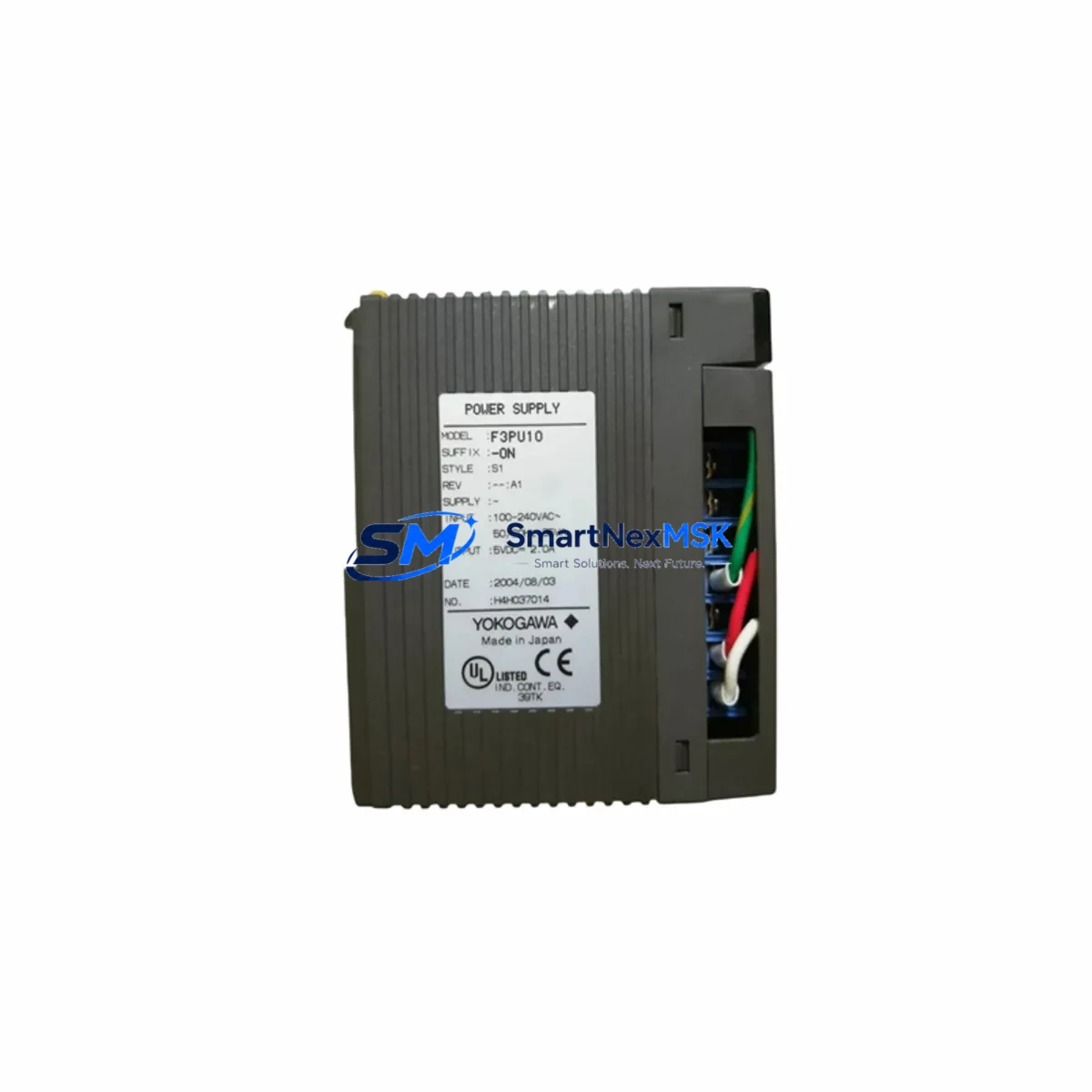
YOKOGAWA F3PU10-0N Retrofit-Ready Power Supply for FA-M3 Control Systems
The YOKOGAWA F3PU10-0N is a DC power supply module purpose-built for the FA-M3 Series programmable controller platform. As legacy FA-M3 installations age and original power supply modules approach end-of-life, the F3PU10-0N has become one of the most sought-after retrofit components for engineers tasked with keeping existing control systems operational without a full platform migration. Whether you are replacing a failed unit on a running production line, upgrading an aging control cabinet, or building a spare-parts inventory for a critical automation system, the F3PU10-0N delivers the electrical performance and mechanical compatibility required for a smooth, low-risk retrofit.
The module provides stable 5 VDC and 24 VDC outputs to power CPU modules, I/O modules, and communication modules mounted on the FA-M3 base unit. Its compact form factor fits directly into the standard FA-M3 rack without any mechanical modification, and its terminal block layout is compatible with existing field wiring, eliminating the need to re-terminate power conductors during replacement. Before installation, engineers should verify the total current draw of all modules installed on the rack — including the F3SP28-3N or F3SP38-6N CPU modules, any F3AD08-6M analog input modules, and F3DA04-1M analog output modules — against the F3PU10-0N’s rated output capacity to ensure the power budget is not exceeded.
When retrofitting the F3PU10-0N into an existing system, the following pre-installation checks are essential to minimize downtime and protect program integrity:
- Power capacity verification: Calculate the combined current consumption of all rack-mounted modules. Include the CPU, all I/O modules such as F3XD32-3F digital input and F3YD32-3H digital output modules, and any installed communication modules like the F3LC11-1F Ethernet communication module.
- Terminal wiring inspection: Confirm that AC input wiring gauge, fusing, and terminal torque specifications match the F3PU10-0N installation requirements. Reuse existing conduit and cable runs where possible to reduce installation time.
- Backplane interface check: Inspect the backplane connector on the base unit for corrosion or mechanical damage before seating the new module. A damaged backplane connector is a common cause of intermittent power faults in aged FA-M3 installations.
- Module address and slot assignment: The power supply module occupies a fixed slot on the FA-M3 base unit. No software address configuration is required, but confirm that the base unit type — whether a 3-slot, 6-slot, or 12-slot chassis — is compatible with the F3PU10-0N form factor.
- Program and HMI continuity: The CPU module retains its ladder logic program in battery-backed RAM during a power supply swap if the battery is healthy. Verify battery status on the F3SP-series CPU before beginning the replacement. If the system uses a FAST/TOOLS or ProSafe-RS HMI, confirm that the HMI communication link to the CPU is restored and all faceplates return to normal state after power-up.
Upgrade Compatibility Table
| Parameter | Detail |
|---|---|
| Compatible Platform | YOKOGAWA FA-M3 Series Programmable Controller |
| Module Type | DC Power Supply Module |
| Output Voltage | 5 VDC / 24 VDC (internal bus) |
| Rack Compatibility | FA-M3 standard base units (3-slot, 6-slot, 12-slot) |
| Backplane Interface | FA-M3 proprietary backplane connector — direct drop-in fit |
| Wiring Compatibility | Existing AC input terminal block wiring reusable without re-termination |
| Communication Impact | None — power supply replacement does not affect CPU program or I/O mapping |
| Replacement Recommendation | Direct replacement for failed or end-of-life F3PU10-0N units; no firmware update required |
| Commissioning Notes | Verify power budget, inspect backplane connector, confirm CPU battery before swap |
| Warranty | 12-Month Warranty — covers manufacturing defects and functional failure under normal operating conditions |
Retrofit Planning for Existing Automation Systems
A successful FA-M3 power supply retrofit begins well before the maintenance window opens. Start by auditing the full module inventory installed in the affected rack. A typical FA-M3 control cabinet in a process plant or discrete manufacturing facility will include a mix of the F3SP28-3N or F3SP58-4S CPU module, F3XD32-3F and F3YD32-3H digital I/O modules, F3AD08-6M analog input modules, and an F3LC11-1F or F3LC12-1F Ethernet communication module for SCADA connectivity. Each of these modules draws current from the power supply bus, and the aggregate load must be within the F3PU10-0N’s rated capacity.
For systems that also include an F3RP61-2L Linux-based module for data logging or OPC-UA communication, note that this module has a higher current draw than standard I/O modules and must be factored into the power budget calculation. Similarly, if the rack includes an F3NC96-0N motion control module for coordinated axis control, its power consumption during servo enable states should be measured under load conditions rather than estimated from nameplate data alone.
Control cabinet wiring should be photographed and documented before any module is removed. Label all terminal connections on the power supply input side. If the existing installation uses a dedicated 24 VDC external power supply for field sensors — a common arrangement in FA-M3 systems where the internal 24 V bus powers only the module logic — confirm that the external supply remains energized during the swap to avoid dropping field sensor signals and triggering spurious alarms in the DCS or SCADA layer.
For sites running YOKOGAWA CENTUM VP or ProSafe-RS in parallel with the FA-M3 controller, coordinate the power supply replacement with the DCS operations team to ensure that any FA-M3 I/O data used as inputs to CENTUM VP function blocks is placed in a safe hold state before the FA-M3 rack loses power. This prevents downstream control loops from responding to stale or zero-value data during the replacement interval.
Downtime Control During System Migration
Minimizing unplanned downtime during a power supply replacement on a live FA-M3 system requires a structured approach. The recommended procedure is to schedule the replacement during a planned maintenance window, pre-stage the F3PU10-0N module on the bench, and verify its output voltages with a calibrated multimeter before bringing it to the field. This eliminates the risk of installing a transit-damaged unit and discovering the fault only after the rack is powered down.
Before removing the existing power supply, place the FA-M3 CPU in STOP mode via the programming tool — typically WIDE Field2 or FA-M3 Programming Tool running on a Windows engineering workstation connected via the F3LC11-1F Ethernet port or a dedicated programming cable. Save a backup copy of the CPU program to the engineering PC and to a CF card if the CPU supports it. This backup protects against the unlikely event of battery-backed RAM data loss during the power interruption.
Once the new F3PU10-0N is seated and the rack is re-energized, confirm that all module status LEDs return to their normal run states before switching the CPU back to RUN mode. Check the F3LC11-1F communication module link status to confirm that the Ethernet connection to the SCADA or HMI system has been re-established. Perform a functional test of representative I/O points — both digital and analog — before releasing the system back to production. Document the replacement in the site maintenance log, including the module serial number, installation date, and post-replacement test results, to support the 12-month warranty claim process if required.
Retrofit Support FAQ
Q: Is the F3PU10-0N a direct drop-in replacement for an existing failed power supply in my FA-M3 rack?
A: Yes. The F3PU10-0N is designed as a direct mechanical and electrical replacement for the same model in FA-M3 base units. No rack modification, rewiring of the AC input terminals, or software reconfiguration is required. Verify the total module load on your rack does not exceed the rated output before installation.
Q: Will replacing the power supply erase the CPU program stored in the FA-M3?
A: The FA-M3 CPU module stores its ladder logic program in battery-backed RAM, which is independent of the power supply module. As long as the CPU battery is in good condition, the program will be retained during the power interruption. We recommend verifying battery status and taking a program backup before beginning any power supply replacement as a precautionary measure.
Q: What commissioning steps are required after installing the F3PU10-0N?
A: After seating the module and restoring AC power, confirm all module status LEDs are normal, verify the CPU returns to RUN mode, check communication link status on any installed Ethernet or serial communication modules, and perform a functional I/O test on representative digital and analog channels. For systems integrated with CENTUM VP or a third-party SCADA, confirm that all data tags are updating correctly before releasing the system to production.
Q: What does the 12-month warranty cover, and how is a claim initiated?
A: The 12-month warranty covers manufacturing defects and functional failures under normal operating conditions from the date of shipment. To initiate a warranty claim, contact our sales team with the module serial number, purchase order reference, and a description of the fault. We will arrange return shipping and provide a replacement or repaired unit within the agreed lead time. Contact: [email protected] | +86 18259474341
© 2026 SMARTNEXMSK. All rights reserved.
Original Source: https://smartnexmsk.com
Contact: [email protected] | +86 18259474341



