
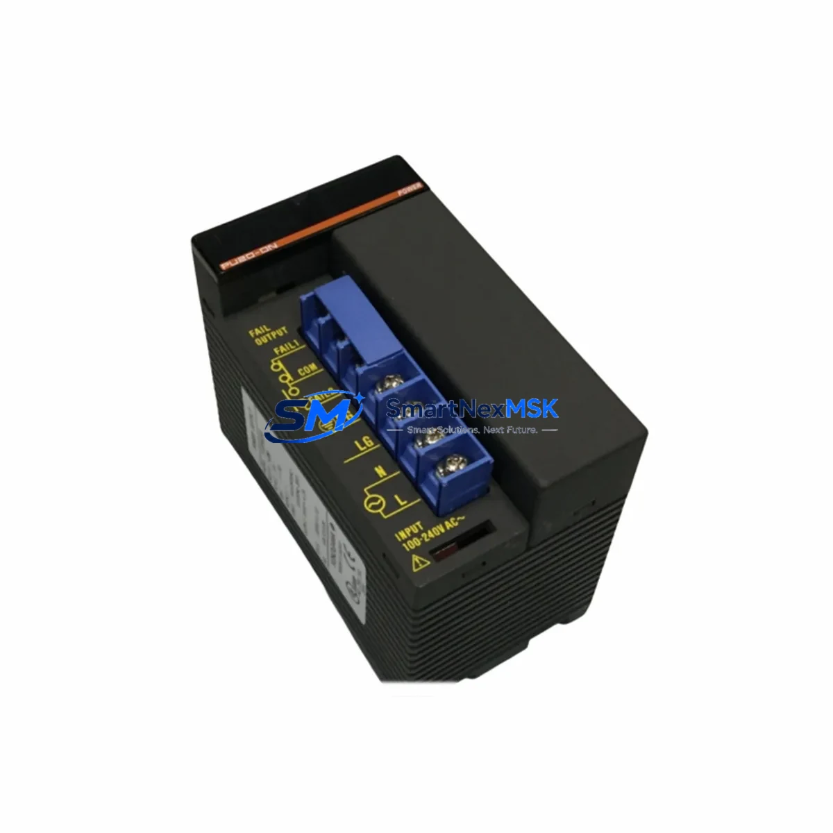
YOKOGAWA F3PU20-0N Maintenance-Ready Spare for FA-M3 Automation
The YOKOGAWA F3PU20-0N is a dedicated power supply module for the FA-M3 series programmable controller platform — one of YOKOGAWA’s most widely deployed industrial automation systems across process manufacturing, utilities, and infrastructure facilities. For maintenance engineers managing aging FA-M3 installations, securing a reliable stock of the F3PU20-0N is a critical element of any preventive maintenance program. Power supply failures are among the leading causes of unplanned PLC downtime, and the F3PU20-0N’s role as the backbone of the FA-M3 rack power distribution makes it a high-priority spare in any control cabinet inventory.
Whether you are responding to an emergency shutdown, executing a scheduled overhaul, or building a strategic spare parts buffer for a long-running production line, the F3PU20-0N delivers the electrical stability and form-factor compatibility required for direct, no-modification installation into existing FA-M3 base units. Our stock is sourced, inspected, and shipped with a 12-month warranty to support your maintenance operations with confidence.
Spare Maintenance Table
| Parameter | Specification / Detail |
|---|---|
| SKU / Part Number | F3PU20-0N |
| Brand | YOKOGAWA |
| Series | FA-M3 (STARDOM / Sequence CPU Platform) |
| Module Type | Power Supply Module |
| Input Voltage | 100–240 VAC, 50/60 Hz (universal input) |
| Output | 5 VDC internal bus power for FA-M3 base unit |
| Mounting | Direct slot installation into FA-M3 base unit (F3BU□□-□N) |
| Compatibility | FA-M3 base units: F3BU04-0N, F3BU05-0N, F3BU16-0N and compatible variants |
| Communication Impact | None — power supply replacement does not affect CPU program or I/O mapping |
| Installation Requirement | Power-off required; verify input wiring polarity and terminal torque spec before energizing |
| Maintenance Interval | Inspect every 2–3 years; replace proactively at first sign of output voltage drift or thermal alarm |
| Application Environment | Industrial control panels, process automation, utilities, infrastructure PLC cabinets |
| Warranty | 12 Months — covers manufacturing defects and functional failure under normal operating conditions |
| Origin | Japan |
| Shipping | In-stock; worldwide express dispatch within 1–2 business days |
Maintenance Planning for Continuous Operation
A power supply module failure in an FA-M3 rack does not occur in isolation — it places stress on every downstream component sharing the internal bus. When replacing the F3PU20-0N, a thorough maintenance inspection should extend to the full control cabinet to prevent secondary failures and ensure the system returns to stable operation.
Begin with the FA-M3 base unit itself. The F3BU04-0N or F3BU16-0N backplane should be inspected for connector pin condition, dust accumulation, and any signs of thermal discoloration near the power slot. A degraded backplane can cause intermittent faults even after a new power supply is installed. Next, verify the CPU module — typically an F3SP□□-□N sequence CPU or an F3RP□□-□N real-time OS CPU — is restarting cleanly and that the program memory has not been corrupted by the power event.
On the I/O side, inspect the digital input modules (such as F3XD□□-□N series) and digital output modules (F3YD□□-□N series) for any blown output transistors or input circuit damage caused by voltage transients during the power failure. Analog I/O modules — including F3AD□□-□N analog input and F3DA□□-□N analog output types — should be verified for signal accuracy after power restoration, as analog circuits can drift following an uncontrolled shutdown.
Communication continuity is equally important. If the FA-M3 system uses an F3LE□□-□N Ethernet communication module or an F3LC□□-□N link module for inter-rack or SCADA connectivity, confirm that network addresses and communication parameters have been retained. In systems with F3SP71-4N or similar CPU modules that support built-in Ethernet, verify the IP configuration and HMI polling cycle has resumed normally.
For cabinets with relay output modules or external relay banks connected to FA-M3 DO channels, inspect relay coil continuity and contact condition — power surges during a PSU failure are a common cause of relay contact welding. Terminal blocks and wiring ferrules at the power input section should also be re-torqued to manufacturer specification. Finally, if the system includes signal isolators between field instruments and FA-M3 analog inputs, confirm isolator output levels are within calibrated range before returning the system to automatic control.
Building a structured spare parts kit around the F3PU20-0N — including at minimum one spare CPU module, one spare Ethernet communication module, and a set of high-wear I/O modules matched to your installed base — is the most effective strategy for reducing mean time to repair (MTTR) across FA-M3 installations with long planned service lives.
Site Replacement Workflow
Replacing the F3PU20-0N on-site is a straightforward procedure when properly planned, and can typically be completed within 30–60 minutes by a qualified maintenance technician. The following workflow is designed to minimize downtime and protect program integrity throughout the replacement process.
Step 1 — Pre-Replacement Verification: Before powering down, confirm the CPU module status indicators show normal operation and that no active alarms are present in the HMI or SCADA system. Back up the CPU program using YOKOGAWA’s WideField3 programming software via the F3SP CPU’s USB or Ethernet port. Record all current I/O status values for post-replacement verification.
Step 2 — Controlled Shutdown: Issue a controlled stop command from the HMI or programming terminal. Switch the CPU to STOP mode before removing AC power from the cabinet. This prevents program execution errors and protects output devices from undefined states during power removal.
Step 3 — Power Supply Removal: Isolate the AC input to the FA-M3 cabinet using the dedicated circuit breaker. Wait a minimum of 30 seconds for internal capacitors to discharge. Disconnect the AC input wiring from the F3PU20-0N terminal block, noting wire positions. Release the module locking mechanism and slide the unit out of the base unit slot.
Step 4 — New Module Installation: Insert the replacement F3PU20-0N into the power supply slot of the FA-M3 base unit until the connector seats fully. Reconnect AC input wiring to the correct terminals (L, N, PE) and re-torque to the specified value. Restore AC power and observe the PWR LED — steady green indicates normal output.
Step 5 — System Restart and Verification: Switch the CPU to RUN mode and confirm all I/O modules initialize correctly. Verify communication links to HMI and SCADA are restored. Compare live I/O values against the pre-shutdown records to confirm system integrity before returning to automatic operation.
Spare Parts Support FAQ
Q1: Is the F3PU20-0N compatible with all FA-M3 base unit models?
The F3PU20-0N is designed for the FA-M3 platform and is compatible with standard FA-M3 base units including the F3BU04-0N, F3BU05-0N, and F3BU16-0N. Always verify the base unit model number against YOKOGAWA’s compatibility documentation before ordering, particularly for older or region-specific FA-M3 configurations.
Q2: How is the F3PU20-0N tested before shipment?
Each unit undergoes functional power-on testing to verify output voltage stability and module initialization. Units are inspected for physical condition, connector integrity, and label legibility. A test report is available upon request. All units ship with a 12-month warranty covering manufacturing defects and functional failure under normal operating conditions.
Q3: Can the F3PU20-0N be replaced without losing the CPU program?
Yes. The FA-M3 CPU module retains its program in non-volatile flash memory independently of the power supply module. Replacing the F3PU20-0N does not erase or modify the CPU program. However, we recommend backing up the program via WideField3 before any maintenance intervention as a standard precaution.
Q4: What is the recommended spare parts strategy for FA-M3 power supply modules?
For production-critical FA-M3 systems, we recommend maintaining at least one F3PU20-0N spare on-site per installed rack. For facilities with multiple FA-M3 racks or systems operating in remote or difficult-to-access locations, a buffer of two to three units is advisable. Long-term supply availability is confirmed — contact our team for volume pricing and scheduled delivery programs.
© 2026 SMARTNEXMSK. All rights reserved.
Original Source: https://smartnexmsk.com
Contact: [email protected] | +86 18259474341



